Hot stripping pliers for ribbon fiber

A ribbon-shaped optical fiber and stripping forceps technology, which is applied in the field of optical fiber stripping devices, achieves the effects of stable clamping, reduced skill requirements, and reduced labor intensity

Active Publication Date: 2012-09-26
BENGBU JIXIN COMM MACHINERY
View PDF3 Cites 15 Cited by
  • Summary
  • Abstract
  • Description
  • Claims
  • Application Information

AI Technical Summary

Problems solved by technology

[0004] The object of the present invention is to provide a ribbon-shaped optical fiber thermal stripper to solve the problem that traditional optical fiber stripping tools in the prior art can only perform stripping operations on single-core optical fibers, and cannot be well applied to stripping optical fibers in ribbons. operational problems

Method used


Image

  • Hot stripping pliers for ribbon fiber
  • Hot stripping pliers for ribbon fiber
  • Hot stripping pliers for ribbon fiber

Examples


Embodiment Construction

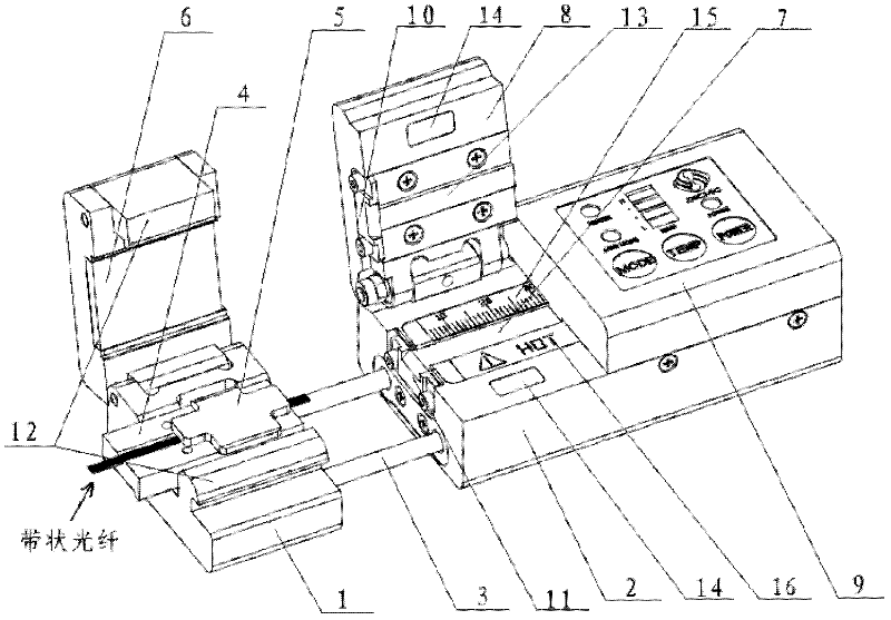
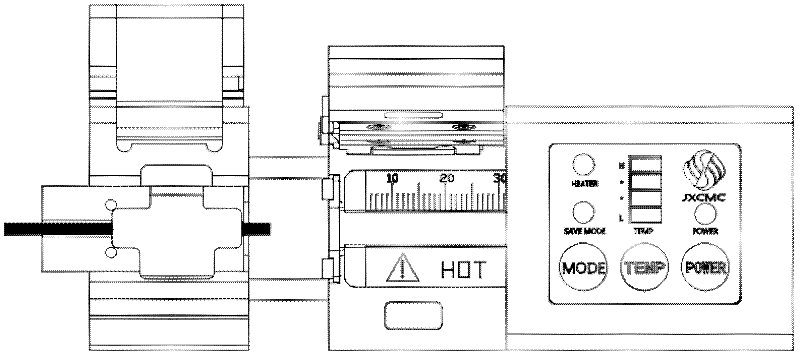
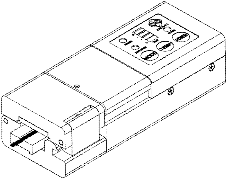
[0021] Such as figure 1 As shown, a strip-shaped optical fiber thermal stripper includes a left base 1 and a right base 2, the left end of the right base 2 is equipped with a linear bearing 3, the left base 1 is slidably mounted on the linear bearing 3, and the left base 1 is hinged with a left cover Plate 6, the bottom plate 4 is installed in the left base 1, the pressure block 5 is installed in the left cover plate 6, and the left cover plate 6 can be attracted to each other when it is tightly closed on the left base 1; the heating plate is installed on the left side of the right base 2 7. A heating system connected to the heating sheet 7 is installed on the right side, and an operation panel 9 connected to the heating system is installed. The right base 2 is hinged with a middle cover plate 8 that can be tightly closed on the heating sheet 7. The right base 2 The upper blade 10 and the lower blade 11 that are cut in half are installed on the left end of the middle cover...


PUM


Abstract

The invention discloses hot stripping pliers for a ribbon fiber. The hot stripping pliers comprise an optical fiber clamp part and a cutting heating part connected through a linear bearing in a sliding manner. The cutting operation adopts a parallel cutting design of an upper blade and a lower blade, and is applicable to fiber stripping operations of a single-core fiber and the ribbon fiber; according to the heating operation, an intelligent heating system is arranged and an optical fiber coating is softened to facilitate the fiber stripping operation of the optical fiber. A design of the linear bearing is adopted, so the release force is small; and the safety and the stability of the operation can be ensured when the optical fiber is drawn to peel off after an optical fiber protecting layer is cut off, and the operation can be finished by one time. The middle heating part adopts a magnet clamping mode so as to facilitate reliable joint of a fiber stripping blade and better strip the coating of the optical fiber. Simultaneously, the skill requirement on an operator is greatly reduced and the popularizing rate of the tool can be greatly improved.

Description

technical field [0001] The invention relates to an optical fiber stripping device, in particular to a strip-shaped optical fiber thermal stripper. Background technique [0002] Optical fiber is a light transmission tool that utilizes the principle of total reflection of light in fibers made of glass or plastic, and has a wide range of applications in the field of communication. During the construction and maintenance of optical fiber laying, it is often necessary to perform fusion splicing operations on optical fibers, so optical fiber fusion splicers are indispensable equipment for optical communication engineering. The fusion splicing operation of the optical fiber is mainly to melt the two optical fibers by emitting an arc, and at the same time use the collimation principle to advance gently to realize the coupling of the optical fiber mode field. [0003] Before the optical fiber fusion operation, the optical fiber needs to be cut and the coating layer is stripped, ...

Claims


Application Information

Patent Timeline
Patent Type & Authority Applications(China)
IPC IPC(8): G02B6/245G02B6/255
Inventor 田林云徐丽尹杰
Owner BENGBU JIXIN COMM MACHINERY
Why Eureka
Try Eureka