
Novel solar photovoltaic junction box

A volt junction box, solar technology, applied in photovoltaic power generation, photovoltaic modules, electrical components and other directions, can solve the problems of large box bottom, poor heat dissipation effect, waste of resources, etc. safety effect

Inactive Publication Date: 2012-09-26
NINGBO CHUANGYUAN PHOTOVOLTAIC TECH
View PDF9 Cites 3 Cited by
  • Summary
  • Abstract
  • Description
  • Claims
  • Application Information

AI Technical Summary

Problems solved by technology

[0002] The solar photovoltaic junction box will generate a lot of heat when it is working. Due to the limitation of heat dissipation performance, it also limits the maximum current it can withstand. In the prior art, the box body is empty, that is, the photovoltaic module is It dissipates heat through the air, so the cooling effect is poor
In addition, the junction box in the prior art has a large box bottom. When installing, the bottom surface of the box bottom is glued and glued to the photovoltaic panel, which is a waste of resources.

Method used


Image

  • Novel solar photovoltaic junction box
  • Novel solar photovoltaic junction box
  • Novel solar photovoltaic junction box

Examples


Embodiment Construction

[0013] The present invention will be described in further detail below in conjunction with the accompanying drawings and specific embodiments.

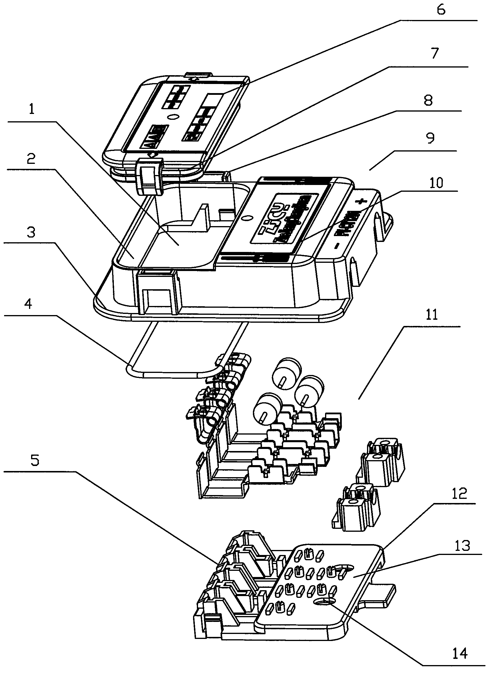
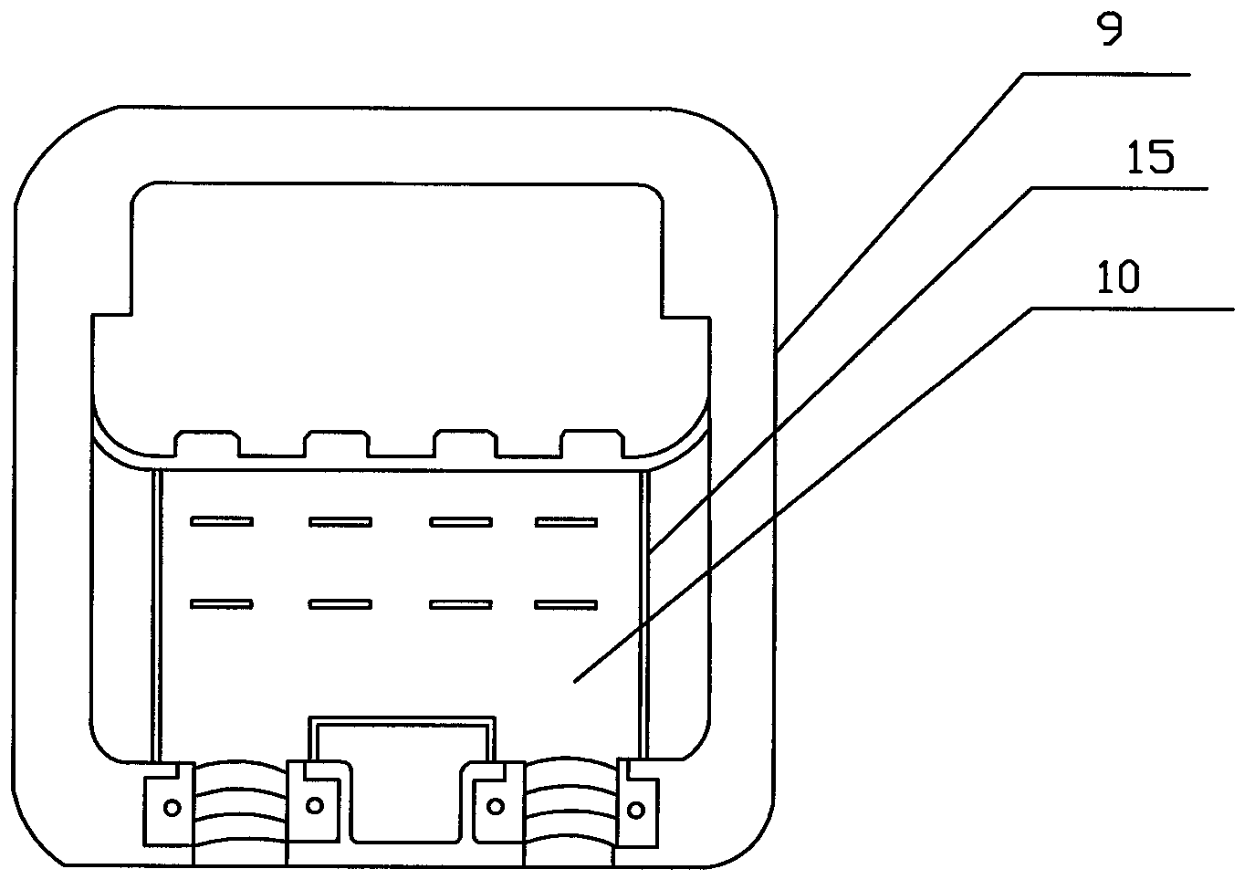
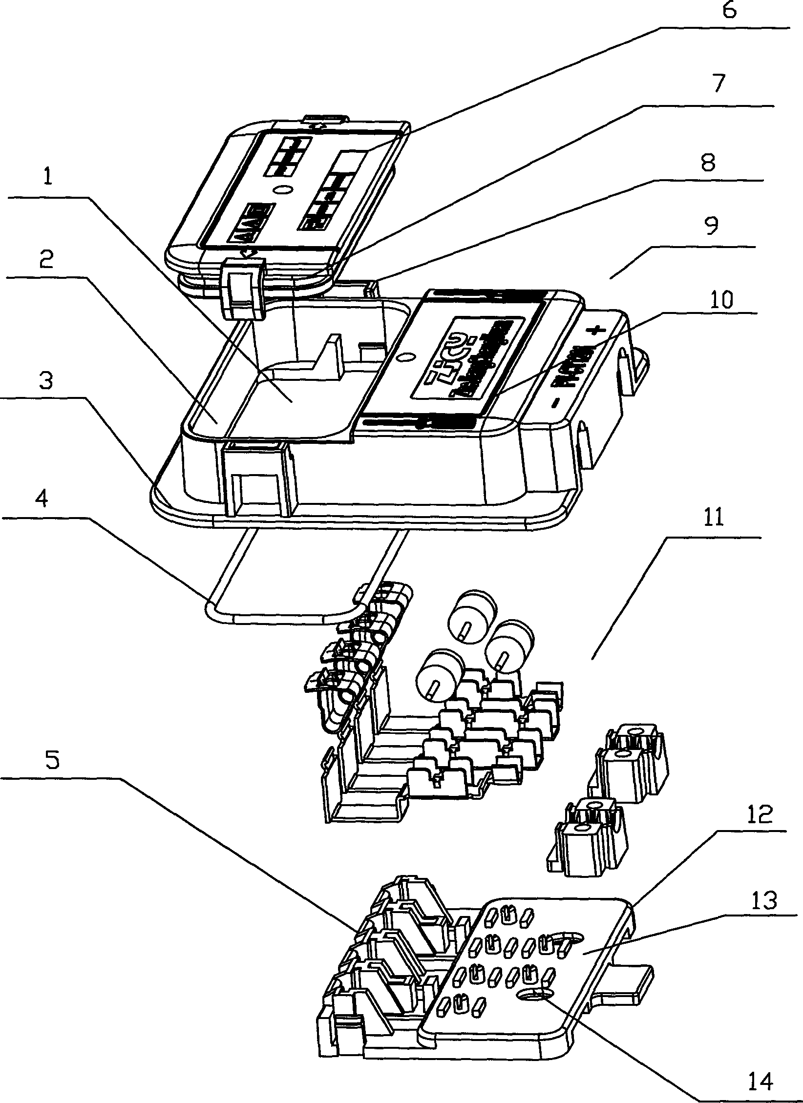
[0014] Such as figure 1 , 2 As shown, a solar photovoltaic junction box includes a box bottom 12 and a box cover 9 that is closed on the box bottom, and a photovoltaic module 11 is arranged on the box bottom 12, and the box cover includes a surrounding frame 2 that forms a closed circle, and the surrounding frame 2 Both are provided with a skirt 3 for smearing glue, the upper end of the surrounding frame is set to be hollow, that is, the hollow end 1, and the lower end of the surrounding frame is provided with an accommodating groove 10 with an opening downward, and the accommodating groove 10 and the bottom of the box jointly form an accommodating cavity. One end of the bus bar at the bottom of the box is a snap-in terminal 5, and one end of the connecting cable at the bottom of the box is a cable end 13, and the snap-in end extend...


PUM


Abstract

The invention relates to a novel solar photovoltaic junction box which comprises a box base and a box cover covered on the box base, wherein the box base is provided with a photovoltaic assembly; the box cover comprises an enclosure frame which is enclosed into a closed loop; the enclosure frame is provided with a skirt edge for smearing glue; the upper end of the enclosure frame is hollow and is a hollow end; the lower end of the enclosure frame is provided with a containing groove with a downward opening; the containing groove and the box base form a containing cavity together; the box base is clamped with one end of a bus bar so as to form a clamping end; the box base is connected with one end of a cable so as to form a cable end; the clamping end extends out of the containing groove; a second box cover is covered on the upper end of the hollow end; the box base is provided with an injection hole; and the injection hole is communicated with the outer part and the inner part of the containing cavity. According to the invention, glue can be poured through the injection hole, the junction box after glue pouring is beneficial to the heat radiation of a bypass diode, the power of the junction box and the circulated current are increased, and also the structure arrangement is reasonable, and the glue pouring amount is reasonable; and additionally, an insulation wall also greatly increases the safety of the junction box.

Description

(1) Technical field [0001] The invention relates to a solar photovoltaic junction box. (2) Background technology [0002] The solar photovoltaic junction box will generate a lot of heat when it is working. Due to the limitation of heat dissipation performance, it also limits the maximum current it can withstand. In the prior art, the box body is empty, that is, the photovoltaic module is It dissipates heat through the air, so the cooling effect is poor. In addition, the junction box in the prior art has a relatively large box bottom. During installation, the bottom surface of the box bottom is glued and glued to the photovoltaic panel, which wastes resources. (3) Contents of the invention [0003] In order to overcome the above-mentioned shortcomings of the prior art, the present invention provides a photovoltaic junction box that can self-fill glue and improve heat dissipation performance. [0004] The technical scheme that the present invention solves its technical pro...

Claims


Application Information

Patent Timeline
IPC IPC(8): H01L31/048H02S40/34
CPCY02E10/50
Inventor 徐艮根
Owner NINGBO CHUANGYUAN PHOTOVOLTAIC TECH
Learn More