
Transmission system and transmission method of non-contact magnetic signals in high hydraulic environment

A non-contact, transmission system technology, applied in the field of non-contact magnetic signal transmission system, can solve the problems such as the limitation of wired signal transmission, achieve the effect of increasing signal-to-noise ratio, avoiding false reception, and increasing reliability

Inactive Publication Date: 2014-03-12
XI AN JIAOTONG UNIV
View PDF4 Cites 0 Cited by
  • Summary
  • Abstract
  • Description
  • Claims
  • Application Information

AI Technical Summary

Problems solved by technology

[0003] In order to solve the problems existing in the above-mentioned prior art, the object of the present invention is to provide a non-contact magnetic signal transmission system and its transmission method in a high hydraulic pressure environment. Eliminates the limitation of wired signal transmission, and improves the sealing and aesthetics of the system

Method used


Image

  • Transmission system and transmission method of non-contact magnetic signals in high hydraulic environment
  • Transmission system and transmission method of non-contact magnetic signals in high hydraulic environment

Examples


Embodiment Construction

[0020] The present invention will be described in more detail below in conjunction with the accompanying drawings.

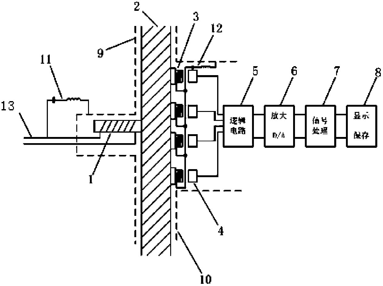
[0021] Such as figure 1 As shown, a non-contact magnetic signal transmission system in a high hydraulic pressure environment of the present invention includes a magnetic pulse transmitting circuit 1, the receiving end of the magnetic pulse transmitting circuit 1 is electrically connected to the signal line 13, and the transmitting of the magnetic pulse transmitting circuit 1 end close to and fixed on the inner side of the austenitic stainless steel chamber wall 2, the inner metal mesh 9 wraps the magnetic pulse generating circuit 1 close to the inner side of the austenitic stainless steel wall 2, and the first high-frequency band-pass filter 11 connects the signal line 13 Electrically connected with the inner metal mesh 9, the outer side of the austenitic stainless steel wall 2 and the corresponding position of the magnetic pulse emission circuit 1 are closely a...


PUM


Abstract

The invention discloses a transmission system and a transmission method of non-contact magnetic signals in a high hydraulic environment. The system comprises a magnetic pulse transmitting circuit of which the receiving end is electrically connected with a signal wire and the transmitting end is clung and fixed in the inner side of the wall of an austenite stainless steel chamber; a magnetic pulse generating circuit is covered by an inner metal net; a signal wire is electrically connected with the inner metal net through a first high-frequency band-pass filter; a second high-frequency band-pass filter and multiple signal amplifying and transmitting circuits are clung and fixed outside the austenite stainless steel wall; the second high-frequency band-pass filter, the signal amplifying and transmitting circuits; and single-shaft magnetic sensors of which the number is the same are covered outside the austenite stainless steel wall through an outer metal net. The transmission method comprises the following steps: switching the signal transmitted through a conductor into a magnetic field signal which can be transmitted in space and can pass through the austenite stainless steel wall to reach a receiving part arranged on the external part of the chamber, and then switching the magnetic field signal into corresponding forms of data to be observed and recorded. With the adoption of the transmission system and the transmission method of the non-contact magnetic signals in the high hydraulic environment, partitioned transmission of the signals is realized and the problem that the wire signal transmission is limited is solved.

Description

technical field [0001] The invention relates to a non-contact magnetic signal transmission system, in particular to a non-contact magnetic signal transmission system and a transmission method thereof in a high hydraulic pressure environment. Background technique [0002] In special engineering environments, the traditional wired signal transmission mode is greatly restricted, especially in extreme environments (deep water, mines, high ionization environments, etc.), its safety and durability have been severely tested, leakage , high wear and maintenance costs and other issues follow. The emergence of non-contact signal transmission makes the above problems solved. Contents of the invention [0003] In order to solve the problems existing in the above-mentioned prior art, the object of the present invention is to provide a non-contact magnetic signal transmission system and its transmission method in a high hydraulic pressure environment. It solves the limitation problem ...

Claims


Application Information

Patent Timeline
Patent Type & Authority Patents(China)
IPC IPC(8): H04B5/00G06K7/00
Inventor 徐明龙张舒文冯勃安增勇翟崇朴
Owner XI AN JIAOTONG UNIV
Learn More