
Monitoring system and monitoring method for image sensors

An image sensor and monitoring system technology, applied in image communication, closed-circuit television system, TV system components, etc., can solve the problems of waste of human resources, increase of system power consumption, increase of system cost, etc., and achieve the effect of reducing power consumption

Active Publication Date: 2012-09-26
BRIGATES MICROELECTRONICS KUNSHAN
View PDF5 Cites 39 Cited by
  • Summary
  • Abstract
  • Description
  • Claims
  • Application Information

AI Technical Summary

Problems solved by technology

However, the pyroelectric infrared sensor also has many disadvantages. First, the anti-interference ability is poor. When various heat sources (such as small animals) appear within the monitoring range of the pyroelectric infrared sensor, False alarms will also occur in the monitoring system, which brings great inconvenience to the work of security personnel and causes a waste of human resources; and the infrared emitted by the human body is easily blocked and cannot be detected; when the ambient temperature is similar to the human body temperature , the pyroelectric infrared sensor will fail and cannot issue an alarm
[0004] However, the monitoring system based on image sensors cannot achieve high-density installation due to the high cost of image sensors for monitoring.
And the traditional monitoring image sensor usually monitors the monitoring area in the high frame rate monitoring mode. The frame rate of the existing image sensor is usually 25fps or 30fps. Since the monitoring image information is coherent only when it is greater than or equal to 25fps, it is beneficial to Real-time monitoring of the monitoring area is realized, but the sensitivity of the image sensor in the high frame rate monitoring mode is low. The system power consumption is greatly increased

Method used


Image

  • Monitoring system and monitoring method for image sensors
  • Monitoring system and monitoring method for image sensors
  • Monitoring system and monitoring method for image sensors

Examples


Embodiment Construction

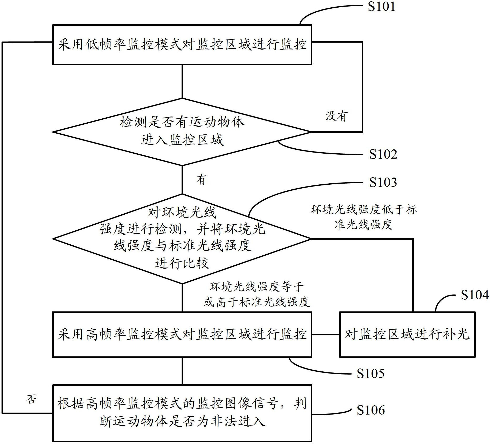
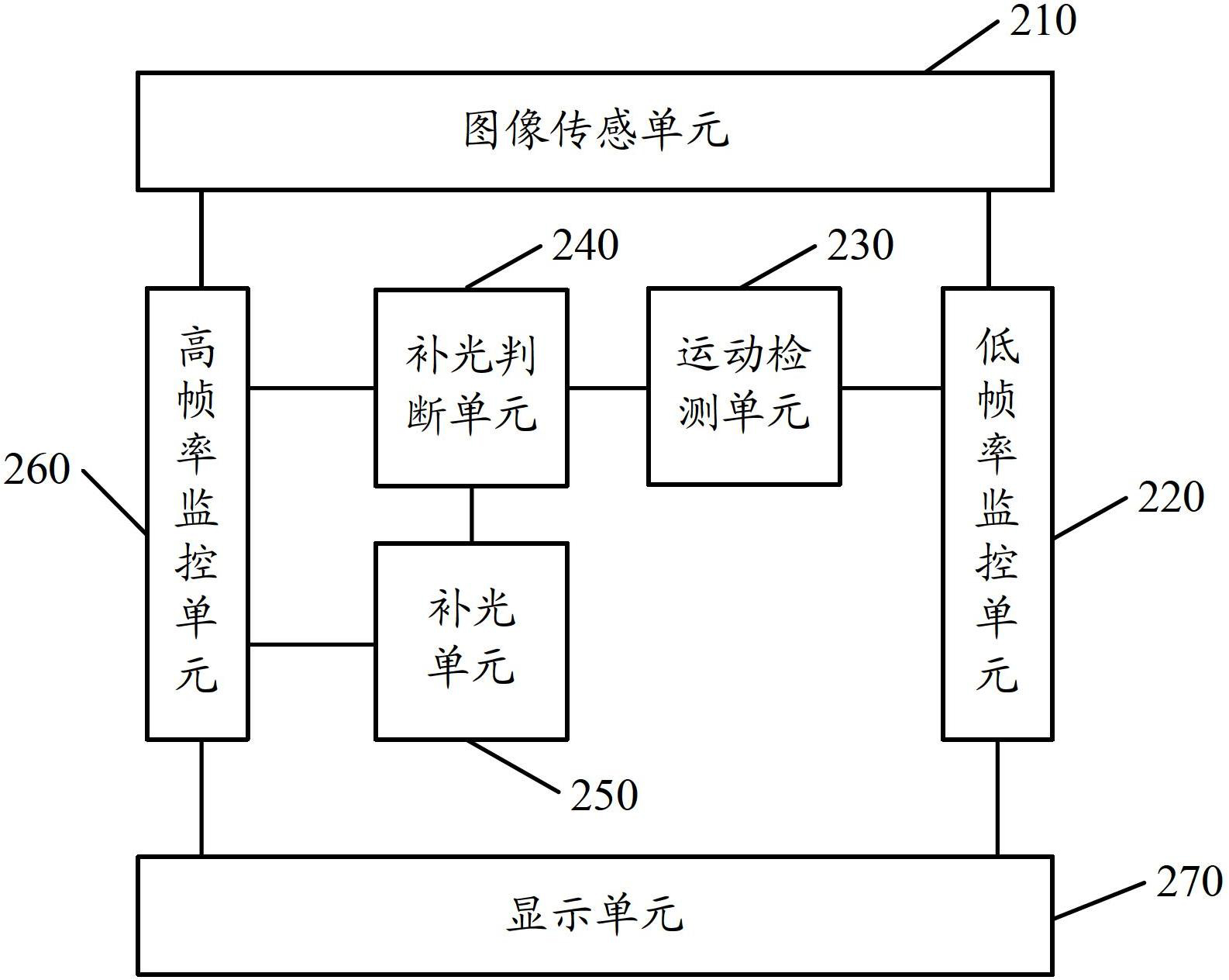
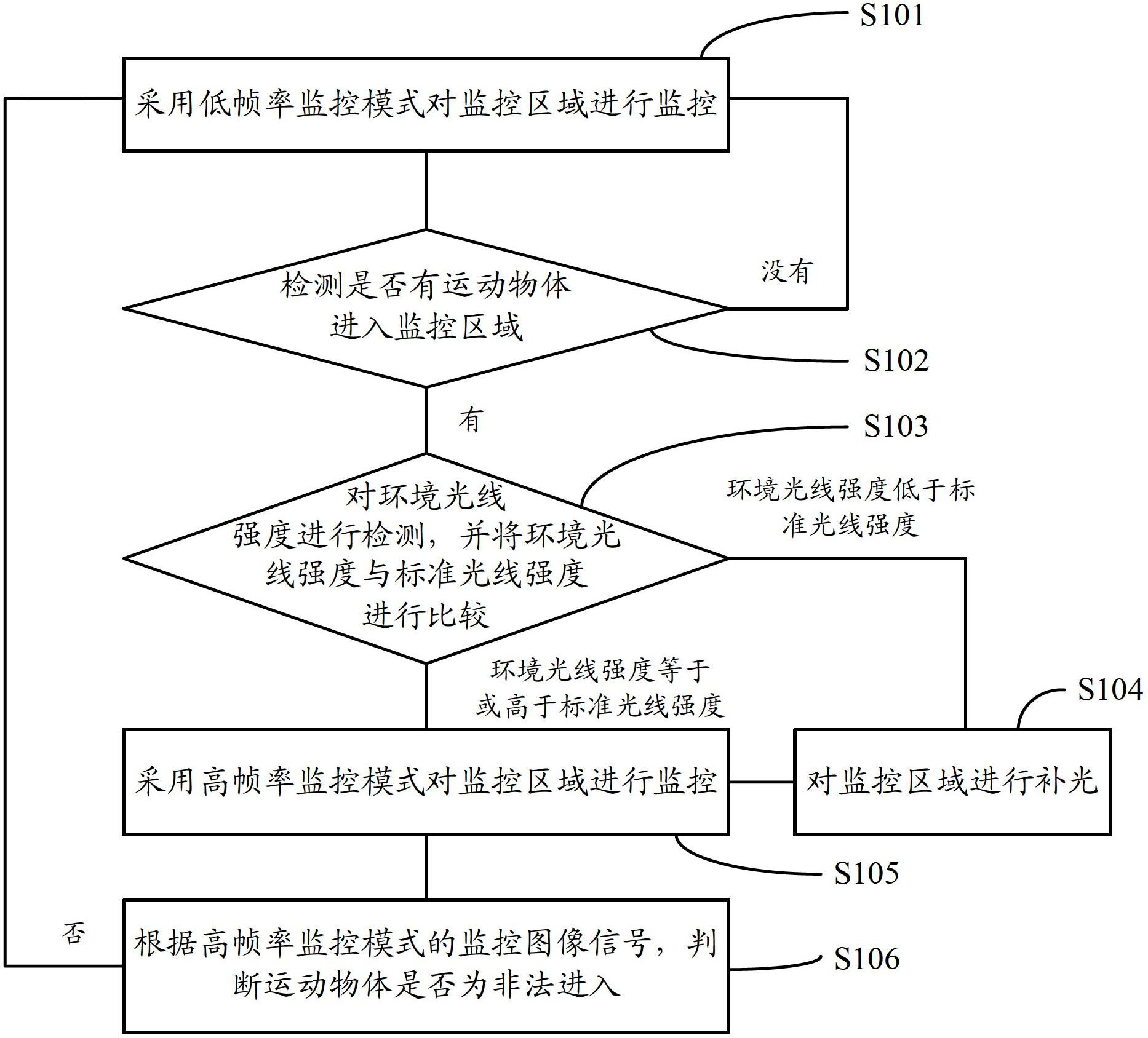
[0047]Because the monitoring image sensor in the prior art usually adopts a high frame rate monitoring mode, but the image sensor sensitivity in the high frame rate monitoring mode is low. Monitoring, but this will increase the system cost and greatly increase the system power consumption. Therefore, an embodiment of the present invention provides an image sensor monitoring system and a monitoring method. The monitoring method includes: using a low frame rate monitoring mode to monitor the monitoring area; when a moving object is found to enter the monitoring area, using a high frame rate The monitoring mode monitors the monitoring area, and selectively fills in light on the monitoring area in the high frame rate monitoring mode. Since the low frame rate monitoring mode is used to monitor the monitoring area, the exposure time of each captured image can be lengthened, so that the signal strength of the obtained monitoring image can become very large, even in a darker environme...


PUM

PropertyMeasurementUnit
Frame rateaaaaaaaaaa

Abstract

The invention relates to a monitoring system and a monitoring method for image sensors. The monitoring method includes: monitoring a monitoring area by means of a low-frame-rate monitoring mode; and monitoring the monitoring area by means of a high-frame-rate monitoring mode when a moving object is discovered to enter the monitoring area, and selectively supplementing light for the monitoring area in the high-frame-rate monitoring mode. When the monitoring area is monitored by means of the low-frame-rate monitoring mode, exposure time for shooting each image can be prolonged, so that the signal intensity of the obtained monitoring image can be high, light supplementing is not needed even if in the dark environment, power consumption can be reduced, and high-quality images can be obtained and the monitoring area can be clearly seen. When the moving object is discovered to enter the monitoring area, the monitoring area is monitored from the high-frame-rate monitoring mode converted into the high-frame-rate monitoring mode, and selective light supplementing is performed, so that effective monitoring of the moving object in the monitoring area can be guaranteed, all-weather monitoring can be realized, and power consumption can be reduced.

Description

technical field [0001] The invention relates to monitoring technology, in particular to an image sensor monitoring system and monitoring method. Background technique [0002] Now many public places and private places are equipped with monitoring systems composed of image sensors, pyroelectric infrared sensors, etc., using the monitoring system to monitor the restricted area, when someone is found to enter the monitoring area, the monitoring system will send out an alarm to remind the security personnel to check the corresponding area. [0003] The pyroelectric infrared sensor is a detection element made of a material with a high pyroelectric coefficient (such as lithium tantalate). The pyroelectric infrared sensor converts the received infrared radiation into a weak voltage signal, which is amplified The external output can detect the movement of people within a certain range, and then send out an alarm. Since the pyroelectric infrared sensor adopts passive detection, the ...

Claims


Application Information

Patent Timeline
IPC IPC(8): H04N7/18H04N5/235
Inventor 罗文哲任张强陈巨
Owner BRIGATES MICROELECTRONICS KUNSHAN
Learn More