Supercharge Your Innovation With Domain-Expert AI Agents!

Controller and led driving circuit with protection function

A technology for light-emitting diodes and protection functions, which is applied in the field of controllers and light-emitting diode driving circuits, and can solve the problems of reliability degradation and damage of semiconductor components.

Active Publication Date: 2012-09-26
GREEN SOLUTION TECH CO LTD
View PDF3 Cites 4 Cited by
  • Summary
  • Abstract
  • Description
  • Claims
  • Application Information

AI Technical Summary

Problems solved by technology

Excessively high operating temperature may reduce the safe operating area (SOA, Safe Operating Area) of the NMOS transistor 130, which may reduce the reliability of semiconductor components and even cause damage.

Method used


Image

  • Controller and led driving circuit with protection function
  • Controller and led driving circuit with protection function
  • Controller and led driving circuit with protection function

Examples


Embodiment Construction

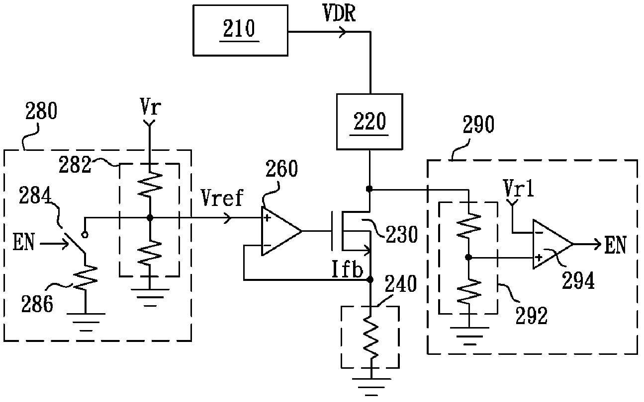
[0056] Please refer to figure 2 , is a schematic circuit diagram of a controller with protection function of the present invention. The controller includes a transistor 230 , a current control unit and a judgment unit 290 , wherein the current control unit includes an error amplifier 260 and a reference voltage generation unit 280 . The transistor 230 can be a built-in controller or an external component, and has a control terminal, a first terminal and a second terminal. Wherein, a first terminal of the transistor 230 is coupled to one terminal of a load 220 , and a driving unit 210 is coupled to the other terminal of the load 220 and provides a driving voltage VDR to drive the load 220 . A current detection unit 240 is coupled to the second terminal of the transistor 230 to generate a current detection signal Ifb. In this embodiment, the current detection unit 240 is a resistor. The error amplifier 260 receives the current detection signal Ifb and the reference voltage V...


PUM


Abstract

A controller with protection function, for controlling a transistor having a control terminal, a first terminal coupled to a load, a second terminal, is disclosed. The controller comprises a judgment unit and a current control unit. The judgment unit is coupled to the transistor and generates a current reducing signal when a potential of the first terminal of the transistor or a voltage difference between the first terminal and the second terminal of the transistor is higher than a preset value. The current control unit is coupled to the control terminal of the transistor for substantially stabilizing the current flowing through the transistor at a preset current value, and reduces the current flowing from the preset current value when receiving the current reducing signal.

Description

technical field [0001] The invention relates to a controller and a light-emitting diode driving circuit, in particular to a controller and a light-emitting diode driving circuit with a current limiting function. Background technique [0002] Please refer to figure 1 , is an existing light-emitting diode drive circuit. The LED driving circuit includes a driving unit 110 , a LED module 120 , an NMOS transistor 130 , a current detection resistor 140 and an error amplifier 160 . The driving unit 110 is coupled to one end of the LED module 120 to provide a driving voltage VDR to drive the LED module 120 to emit light. The NMOS transistor 130 is coupled to the other end of the LED module 120 to control the magnitude of the current flowing through the LED module 120 according to a control signal. The current detection resistor 140 is coupled to the NMOS transistor 130 to detect the magnitude of the current flowing through the LED module 120 and generate a current detection signa...

Claims


Application Information

Patent Timeline
Patent Type & Authority Applications(China)
IPC IPC(8): H05B37/02H05B44/00
CPCH05B37/02H05B33/089Y02B20/341H05B45/50Y02B20/30H03K17/0822
Inventor 余仲哲李立民徐献松
Owner GREEN SOLUTION TECH CO LTD
Features
  • R&D
  • Intellectual Property
  • Life Sciences
  • Materials
  • Tech Scout
  • Unparalleled Data Quality
  • Higher Quality Content
  • 60% Fewer Hallucinations
Learn More