
Hybrid drive device

A driving device and hybrid technology, which is applied in the direction of power devices, hybrid vehicles, pneumatic power devices, etc., can solve the problems of the first shaft becoming longer and not suitable for loading on vehicles, etc., achieve compact structure and improve vehicle loading performance Effect

Active Publication Date: 2012-09-26
AISIN AW CO LTD
View PDF9 Cites 1 Cited by
  • Summary
  • Abstract
  • Description
  • Claims
  • Application Information

AI Technical Summary

Problems solved by technology

Although it is conceivable to apply the above-mentioned cone-ring type CVT to a hybrid drive device, the conical-shaped friction wheel of this cone-ring type CVT is formed in an axially long structure, and the input side friction wheel is arranged together with the electric motor. On the first shaft which is coaxial with the output shaft of the above-mentioned engine, the first shaft will become longer and not suitable for the vehicle
In addition, the above-mentioned Patent Document 2 also describes an embodiment in which the electric motor is arranged on a shaft other than the first shaft. However, in either case, the electric motor is arranged at a position that does not overlap with the conical ring type CVT in the axial direction. A dedicated axial space is required for the electric motor

Method used


Image

  • Hybrid drive device
  • Hybrid drive device
  • Hybrid drive device

Examples


Embodiment Construction

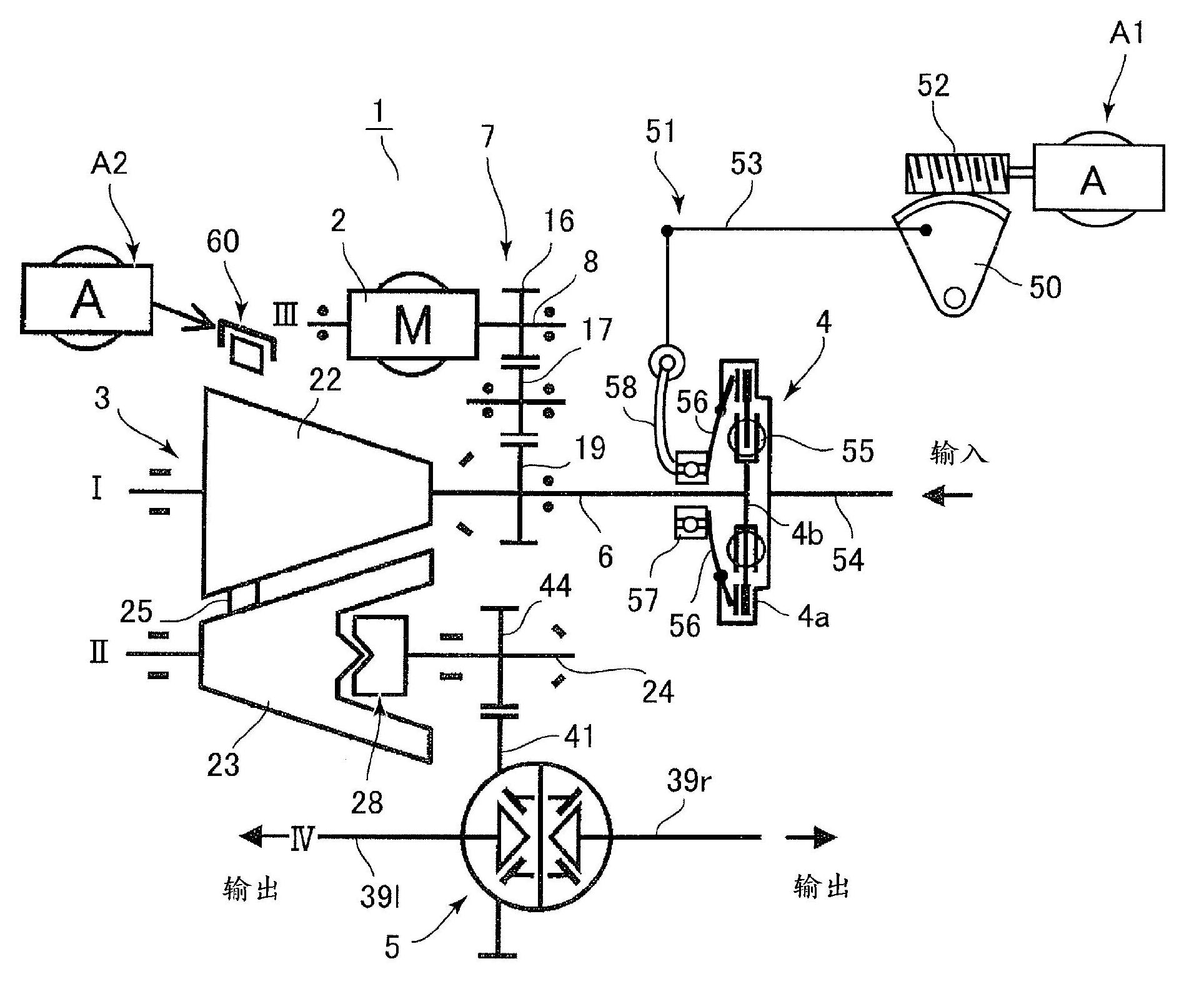
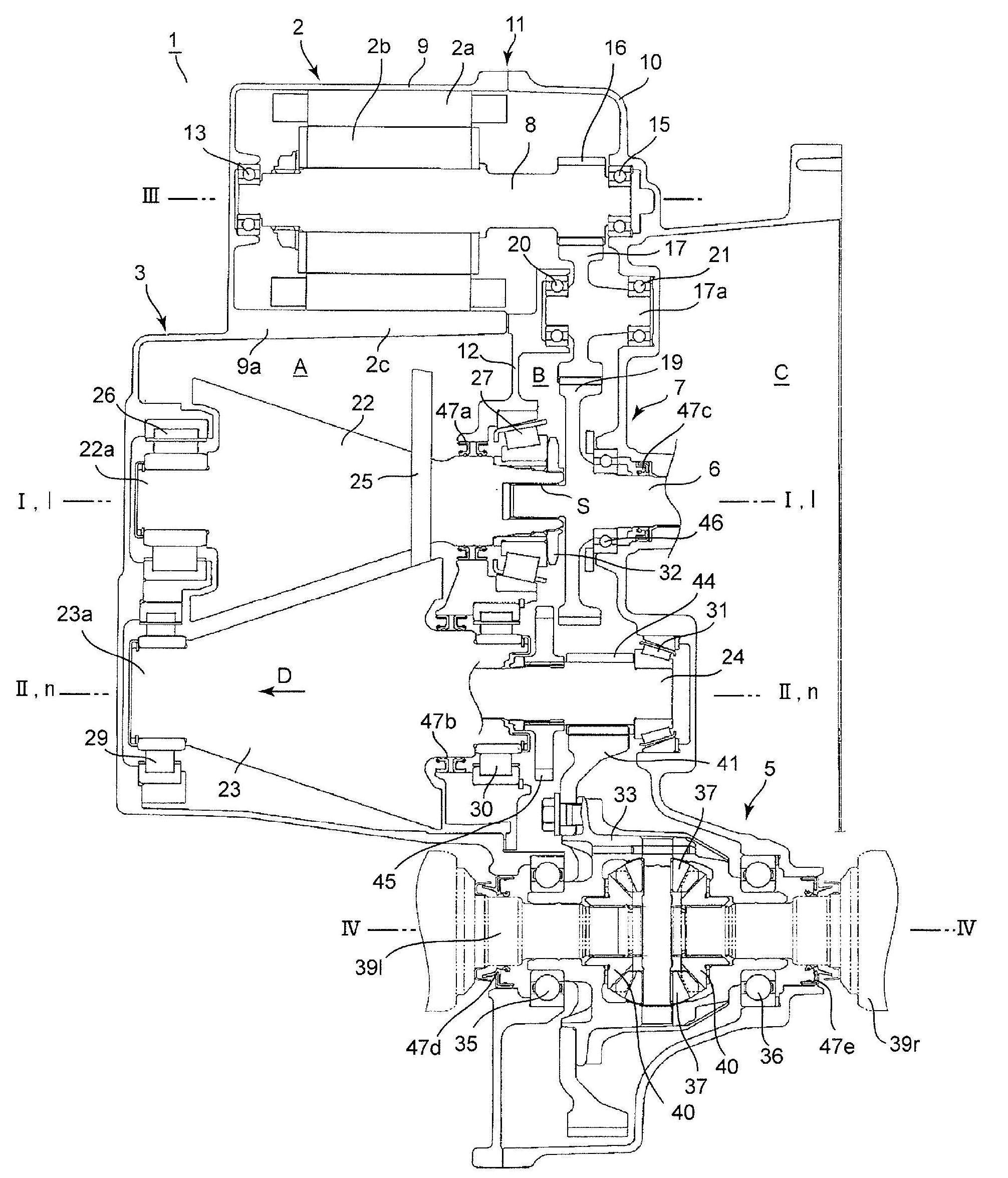
[0041] A hybrid drive device to which the present invention is applied will be described with reference to the drawings. Such as figure 1 and figure 2 As shown, the hybrid drive device 1 includes: an electric motor 2 , a conical friction ring type continuously variable transmission (conical ring type CVT) 3 , a differential device 5 , and an output shaft 54 ​​of an engine (not shown) connected via a clutch 4 . The input shaft 6, and the gear transmission 7. The respective devices and shafts described above are accommodated in a housing 11 composed of two housing members 9 , 10 combined, and the housing 11 is partitioned into a first space A and a second space B by a partition wall 12 in an oil-tight manner.

[0042] The electric motor 2 has a stator 2a fixed to the first case member 9 and a rotor 2b provided on the output shaft 8, one end of the output shaft 8 is rotatably supported by the first case member 9 via a bearing 13, and the other is One end is rotatably supporte...


PUM


Abstract

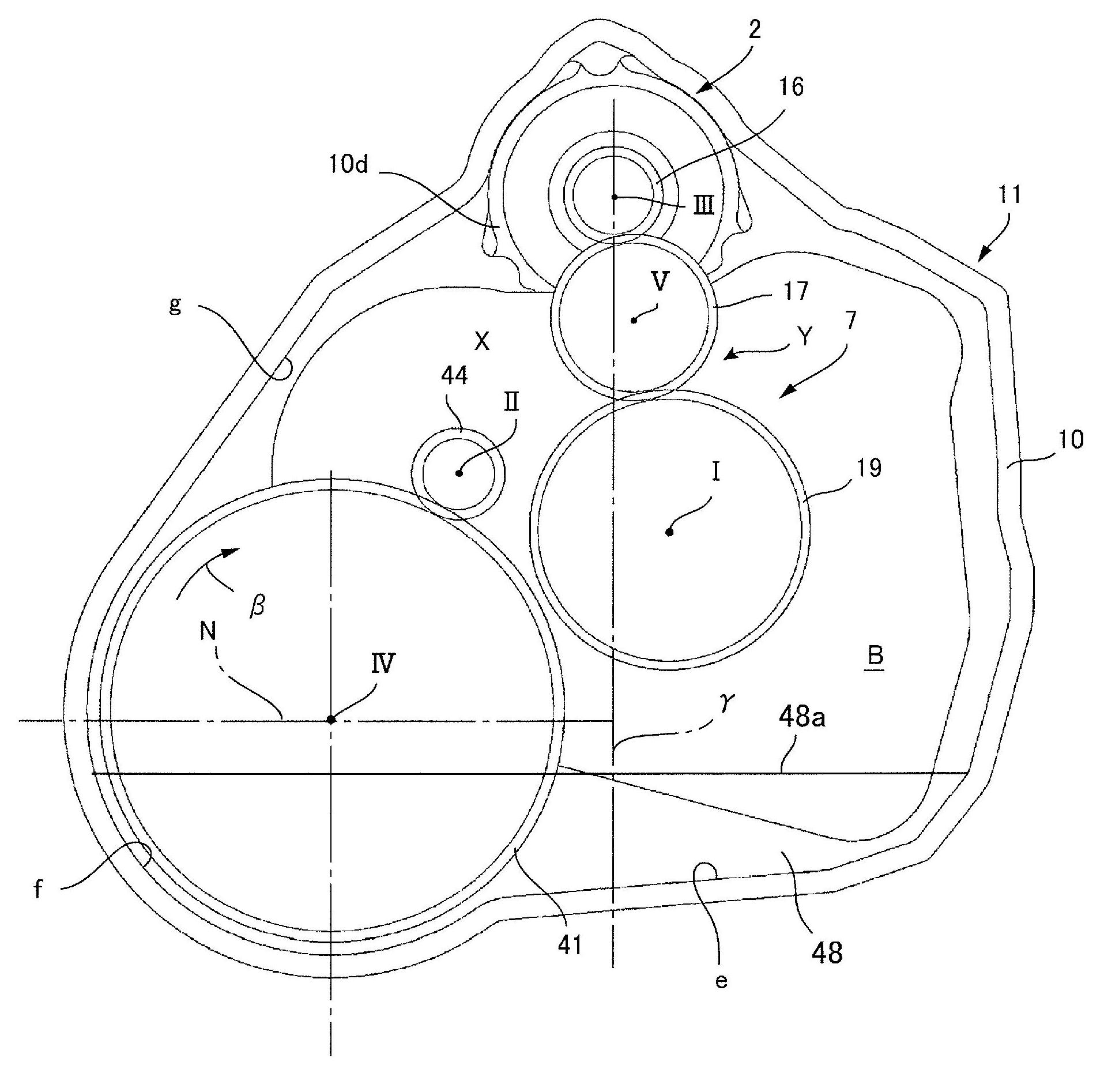
A cone ring CVT is applied in the disclosed hybrid drive device, and a compact arrangement is used for the device overall. An input-side friction gear (22) is disposed at a first shaft (I) that is coaxial with an engine output shaft, an output-side friction gear (23) is disposed at a second shaft (II), and an electric motor (2) is disposed at a third shaft (III) that is parallel to the first shaft and the second shaft. The electric motor (2) and the cone ring CVT (3) are disposed in a manner so as to partially overlap in the axial direction. The third shaft (III) is disposed above the second shaft (II) and on the same side as the first shaft (I) with respect to a vertical line (v-v) that passes through said second shaft.

Description

technical field [0001] The present invention relates to a hybrid drive device capable of driving wheels using an engine and an electric motor, and more specifically, relates to a hybrid drive device in which an electric motor and a conical friction ring type continuously variable transmission (cone ring type CVT) are integrated . Background technique [0002] Conventionally, among hybrid drive devices that drive wheels using an engine and an electric motor, a hybrid drive device that combines a single electric motor and a continuously variable transmission is known. Generally, as the continuously variable transmission device for the hybrid drive device, a belt-type continuously variable transmission device is used. The belt-type continuously variable transmission device consists of a pair of pulleys and a metal belt (or chain) wound around these pulleys. ) form, and by changing the effective diameter of the pulley to carry out infinitely variable speed. [0003] On the oth...

Claims


Application Information

Patent Timeline
Patent Type & Authority Applications(China)
IPC IPC(8): B60K6/40B60K6/36B60K6/485B60K6/543F16H15/22F16H15/42
CPCY02T10/6226Y02T10/7077Y02T10/6221Y02T10/62
Inventor 香山和道神谷美纱纪梅田秀行高桥昭次前野克弘榊原文彦小川亮太白井久则
Owner AISIN AW CO LTD
Learn More