Winding machine

A wire winding machine and frame technology, which is applied in the field of wire winding machines, can solve the problems of potential safety hazards, time-consuming and labor-intensive work, and low work efficiency, and achieve the effects of improving work efficiency, safe operation, and ingenious and reasonable structure

Inactive Publication Date: 2012-10-03
WUXI PINGSHENG SCI & TECH
View PDF5 Cites 13 Cited by
  • Summary
  • Abstract
  • Description
  • Claims
  • Application Information

AI Technical Summary

Problems solved by technology

Existing wire winding machines usually use a support shaft to support the I-shaped wheel. After the winding is completed, it is time-consuming and laborious to replace the I-shaped wheel, the work efficiency is very low, and there are potential safety hazards

Method used


Image

  • Winding machine
  • Winding machine
  • Winding machine

Examples


Embodiment Construction

[0015] The present invention will be further described below in conjunction with specific drawings and embodiments.

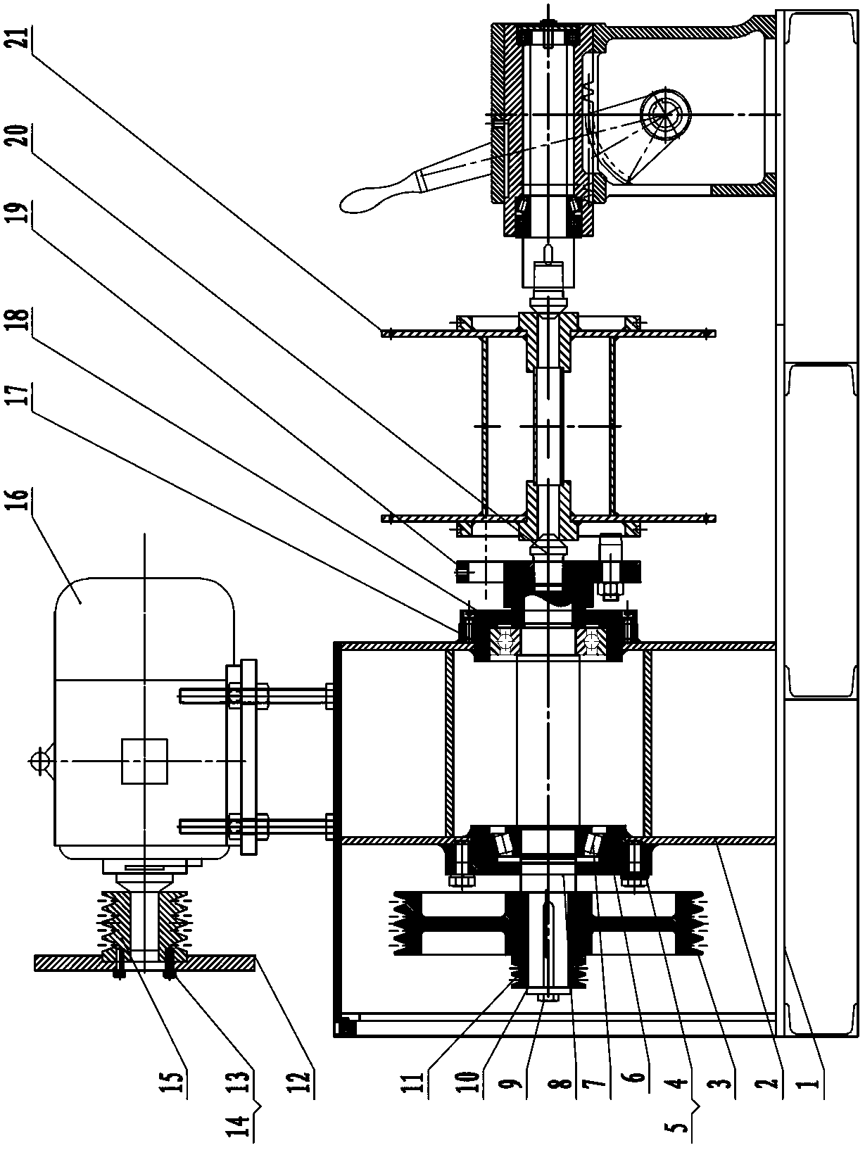
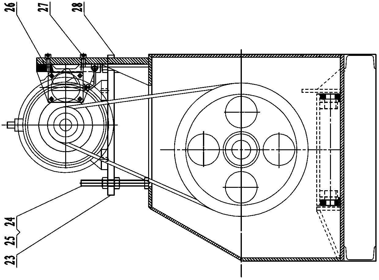
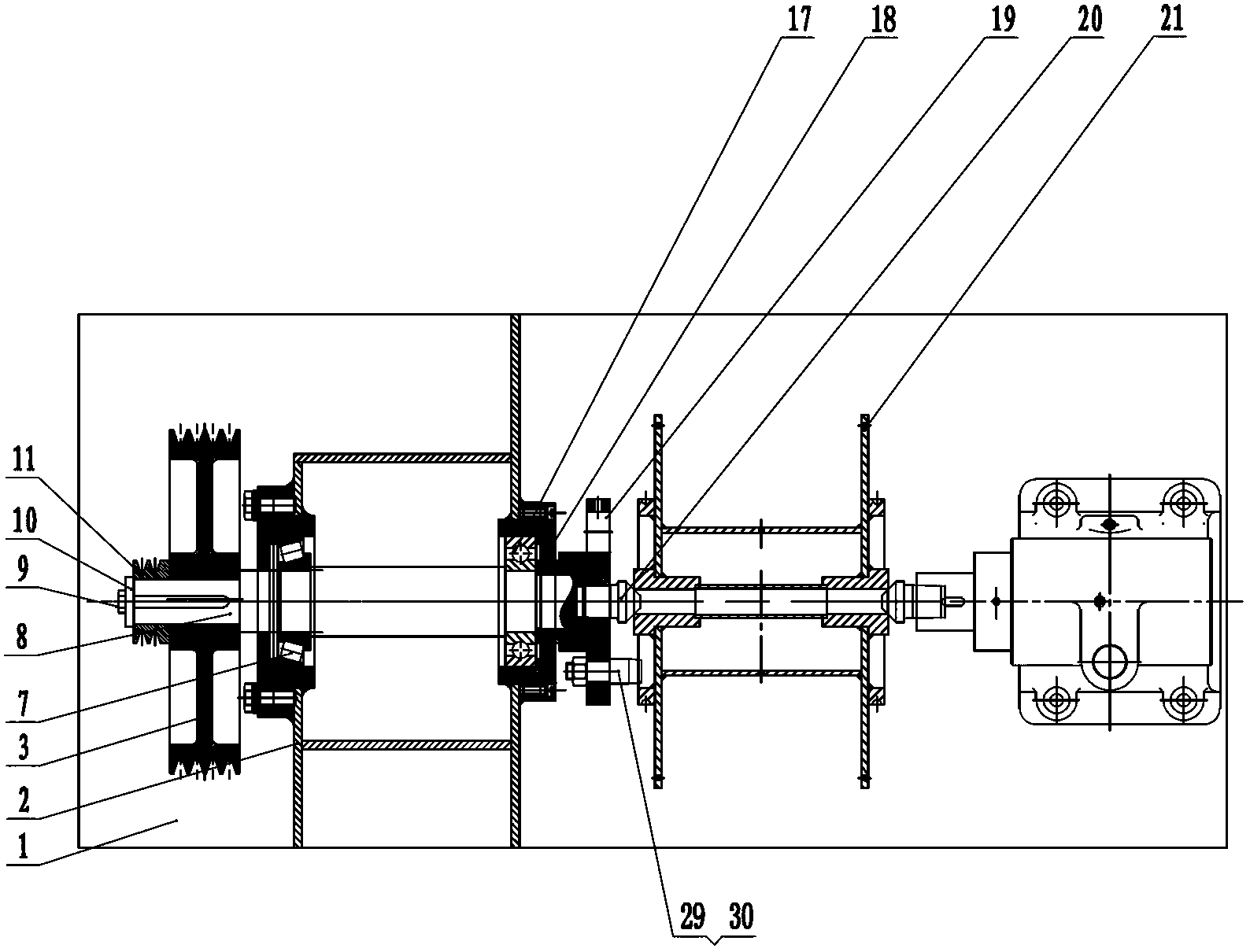
[0016] As shown in the figure: the winding machine in the embodiment mainly includes a frame 1, an active fixed top device is installed on one end of the frame 1, and a passive mobile top device is installed on the other end of the frame 1, and the active fixed top device is installed on the other end of the frame 1. The device cooperates with the passive mobile top device to support and drive the spool 21.

[0017] Such as Figure 1~Figure 3 As shown, the active fixed top device is mainly composed of a head frame 2, a passive pulley 3, a rear screw 4, a spring pad 5, a transparent cover 6, a rear bearing 7, a fixed shaft 8, a screw 9, a gland 10, and a reversing driving pulley 11 , brake disc 12, screw 13, spring pad 14, driving pulley 15, motor 16, front bearing 17, front transparent cover 18, dial 19, fixed top 20, motor bottom plate 23, long screw 24, nut ...


PUM


Abstract

The invention relates to a winding machine. The winding machine comprises a rack, and is characterized in that a center actively fixing device is mounted at one end of the rack, a center passively moving device is mounted at the other end of the rack, and the center actively fixing device is matched with the center passively moving device so as to support and drive a H-shaped wheel. The winding machine is ingenious and reasonable in structure. The H-shaped wheel is supported and driven by matching the center actively fixing device with the center passively moving device and is time-saving and labor-saving to replace. The working efficiency can be greatly improved and the operation is safe.

Description

technical field [0001] The invention relates to wire winding equipment in the metal product industry, in particular to a wire winding machine. Background technique [0002] With the continuous development of the metal products industry, high speed, high efficiency, low cost, and strong process adaptability have become the pursuit goals of enterprises. In the production process of metal cables, winding machines are widely used equipment. Existing wire winding machines usually use a support shaft to support the I-shaped wheel. After the winding is completed, it takes time and effort to replace the I-shaped wheel, the work efficiency is very low, and there are potential safety hazards. Contents of the invention [0003] The purpose of the present invention is to overcome the deficiencies in the prior art and provide a winding machine with ingenious and reasonable structure, time-saving and labor-saving replacement of the I-shaped wheel, greatly improved work efficiency, and ...

Claims


Application Information

Patent Timeline
Patent Type & Authority Applications(China)
IPC IPC(8): B21C47/28B65H54/553
Inventor 顾康建
Owner WUXI PINGSHENG SCI & TECH
Why Eureka
Try Eureka