Steering system with coupling of electric drive tracked vehicle steering motor and unilateral drive motor

A technology for steering motors and driving motors, which is applied in electric vehicles, steering mechanisms, non-deflectable wheel steering, etc., and can solve problems such as excessive power of one-sided driving motors and difficulty in stepless steering

Active Publication Date: 2012-10-03
BEIJING INSTITUTE OF TECHNOLOGYGY
View PDF5 Cites 27 Cited by
  • Summary
  • Abstract
  • Description
  • Claims
  • Application Information

AI Technical Summary

Problems solved by technology

[0004] The purpose of the present invention is to solve the problem that the power of the single-side drive motor is too large when the double-side drive motor drives the tracked vehicle to realize electronically controlled low-speed steering, and when the medium-speed steering and high-speed steering are performed, it aims at the realization of the horizontal-axis double-side drive motor-driven crawler vehicle. Due to the difficulty of step steering, an electric drive track that can reduce the power of the unilateral drive motor, increase the torque and power of the outer driving wheel through the power coupling of the steering motor and the outer drive motor to meet the power required for steering, and realize stepless steering The vehicle steering motor is coupled with the unilateral drive motor to drive the steering system

Method used


Image

  • Steering system with coupling of electric drive tracked vehicle steering motor and unilateral drive motor
  • Steering system with coupling of electric drive tracked vehicle steering motor and unilateral drive motor
  • Steering system with coupling of electric drive tracked vehicle steering motor and unilateral drive motor

Examples


Embodiment Construction

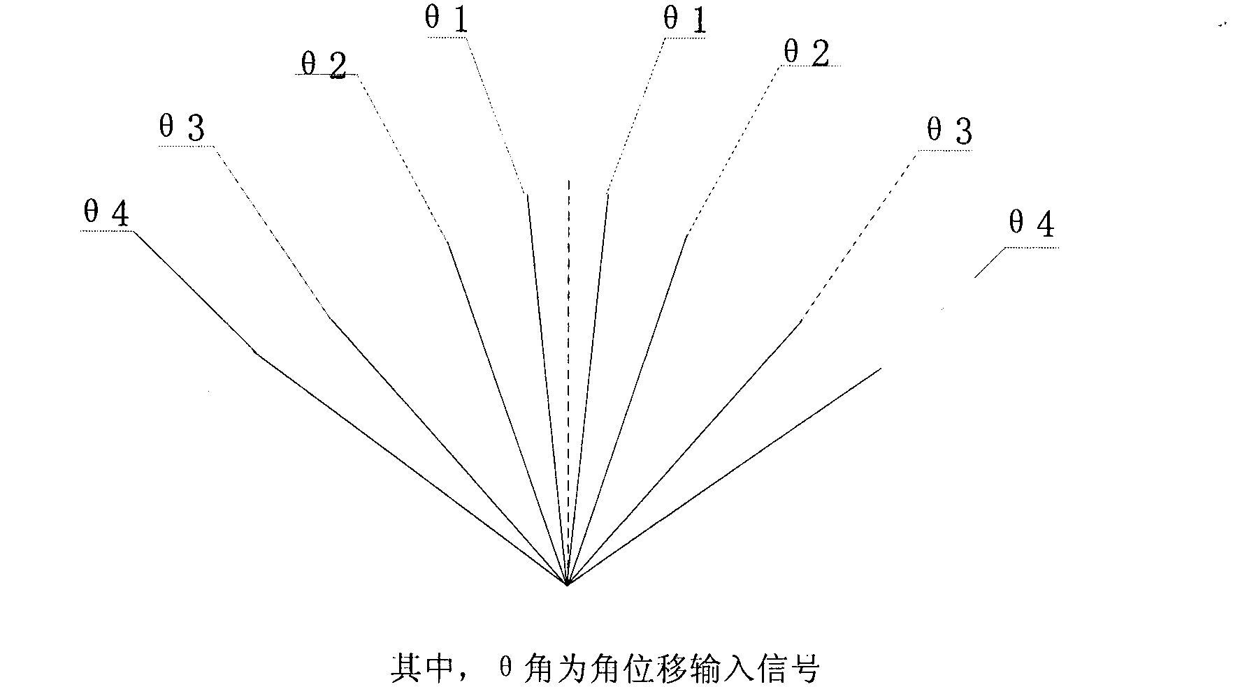
[0022] According to the steering wheel angle such as image 3 As shown, to judge whether the vehicle is turning left or right, take the vehicle turning left as an example:

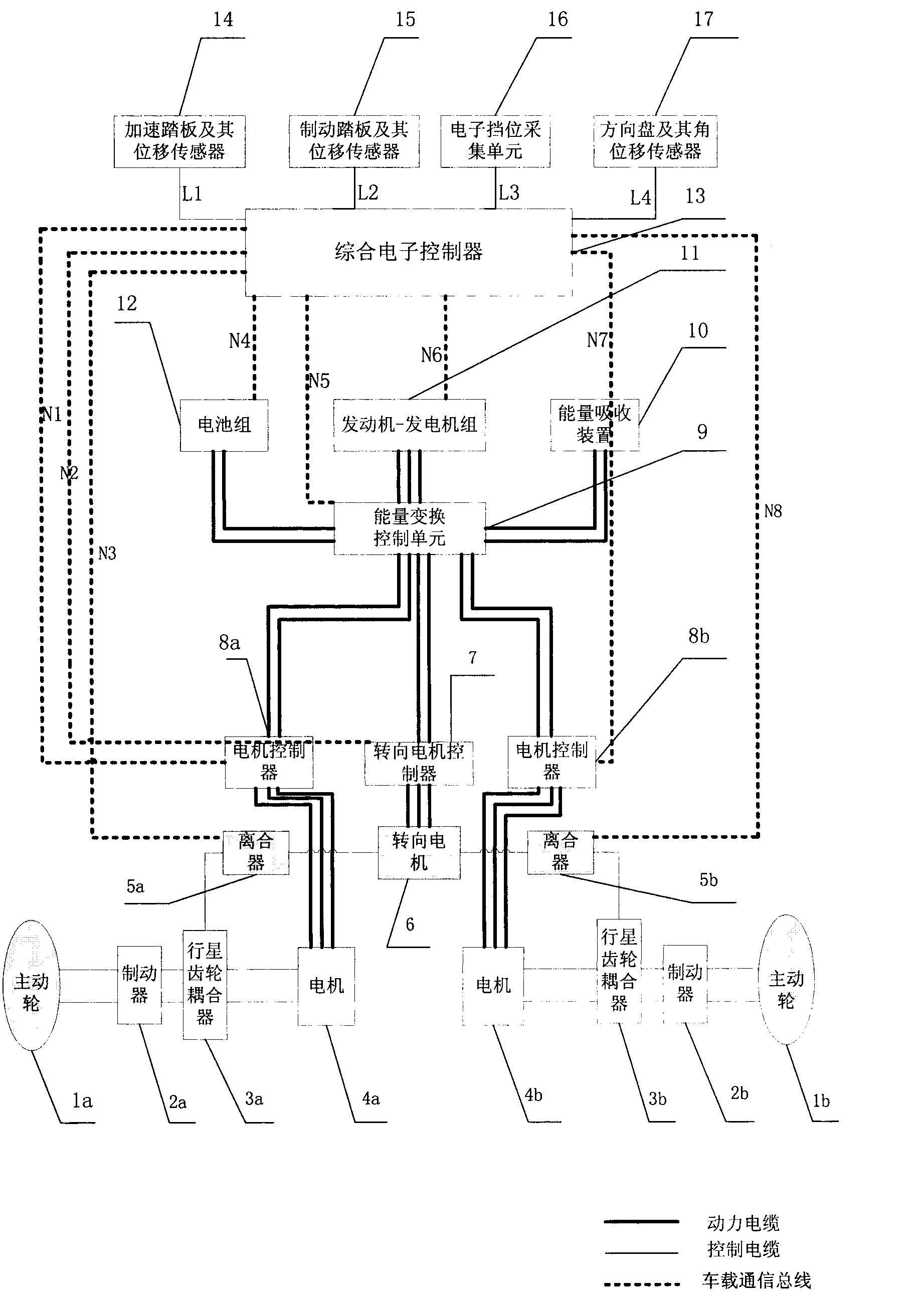
[0023] According to the signals collected by the accelerator pedal and steering wheel sensors, the accelerator pedal and its position sensor 14 will send the desired rotational speed of the vehicle to the integrated controller, and the steering wheel and its angular displacement sensor 17 will send the expected steering radius to the integrated electronic controller 13, and the integrated electronic control The controller 13 judges according to the angular displacement, distributes the relative steering radius, and inputs the torque signal T1 to the inner drive motor controller 8a and the torque signal T2 to the outer drive motor controller 8b respectively. Here, first define the positive and negative of the torque: if the torque is in the same direction as the rotational speed or the changing trend of the...


PUM


Abstract

The invention relates to a steering system with coupling of an electric drive tracked vehicle steering motor and a unilateral drive motor, which is employed to the steering running of bilateral motor drive tracked vehicles. The steering system comprises a mechanical system and an electrical system, wherein the electrical system comprises a power system and a control system. The electronic differential steering mode is used when the power needed by steering is less than the maximum power of the unilateral motor; and the steering is realized by mechanical coupling when the power needed by steering is greater than the maximum power of the unilateral motor. A composite electronic controller controls the separation of the inside electromagnetic clutch and the combination of an outside electromagnetic clutch by a CAN (controller area network) bus, so that the steering motor runs through the outside electromagnetic clutch and an outside planetary coupler orderly, and then is coupled with the power of an outside drive motor by the outside planetary coupler so as to drive the outside driver wheel, so that the power requirement of the steering motor is satisfied.

Description

technical field [0001] The invention relates to a steering system coupled with a steering motor of an electrically driven crawler vehicle and a single-side driving motor, which is used for steering and driving of a crawler vehicle driven by a double-side motor. Background technique [0002] The steering of tracked vehicles is different from that of wheeled vehicles. For tracked vehicles, steering changes the speed of the two tracks. Although conventional high-speed tracked vehicles rely on two sets of independent automatic transmissions to change the speed of the two tracks, the principle It is still a clutch-braking steering mechanism. Such a mechanism has disadvantages such as high cost, complex structure, heavy weight, fast wear, and low load capacity. What adopted is that the power system is separated from the steering system, but such a structure still has problems such as relatively complicated structure and unsatisfactory steering controllability. [0003] In today's...

Claims


Application Information

Patent Timeline
Patent Type & Authority Applications(China)
IPC IPC(8): B62D11/04B60L15/32
Inventor 翟丽王倩男柳龙
Owner BEIJING INSTITUTE OF TECHNOLOGYGY
Why Eureka
Try Eureka