Polysilicon reducing furnace
A reduction furnace and polysilicon technology, applied in silicon and other directions, can solve the problems of high energy consumption of polysilicon, loose polysilicon rods, and low quality, and achieve the effects of improving quality, reducing energy consumption and uniform gas distribution.
- Summary
- Abstract
- Description
- Claims
- Application Information
AI Technical Summary
Problems solved by technology
Method used
Image

Examples
Embodiment 1
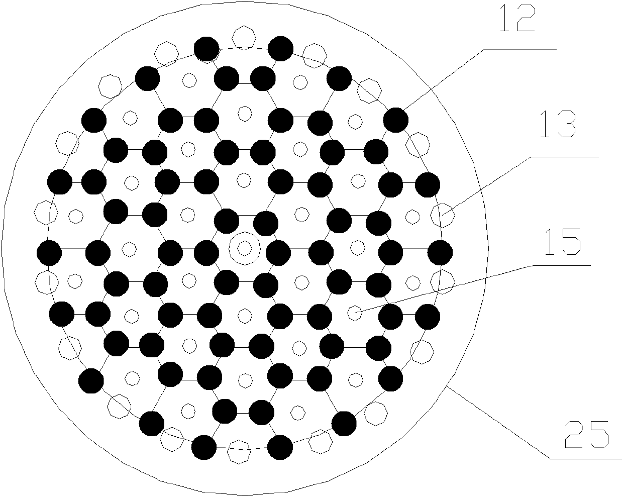
[0039] The polysilicon reduction furnace disclosed in this embodiment includes a furnace body and a chassis, and the structural diagram of the chassis is as follows figure 2 As shown, there are many pairs of evenly distributed electrodes 12 on the chassis 11, wherein the electrodes 12 are arranged in a honeycomb shape, specifically:
[0040] The center of the chassis 11 has six electrodes, the six electrodes 12 are arranged in a regular hexagon with the center of the chassis 11 as the center point, and the six electrodes 12 are respectively located at the six vertices of the regular hexagon place;
[0041] With the regular hexagon as the center, other electrodes are arranged outward in sequence, and the connection line of the outermost electrode 12 is approximately a circle with the center of the chassis as the center.
[0042]In other words, first make a regular hexagon with the center of the chassis as the center point, set an electrode 12 at each vertex of the regular hex...
Embodiment 2
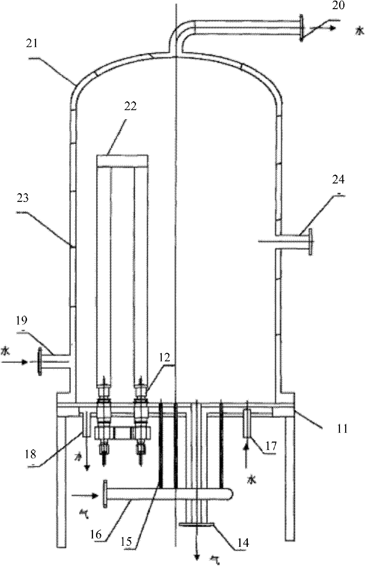
[0049] The front view of the polysilicon reduction furnace disclosed in this embodiment is as follows: image 3 As shown, the top view of the reduction furnace chassis is still as figure 2 As shown, the silicon core arrangement of the reduction furnace is as follows Figure 4 As shown, the difference between this embodiment and the previous embodiment is that in this embodiment, combined with the overall structure of the reduction furnace, the specific dimensions of the various parts of the reduction furnace, the arrangement of silicon cores, etc. are described in detail. Still taking the reduction furnace with 36 pairs of electrodes on the chassis as an example for illustration.
[0050] see Figure 2-Figure 4 , the polysilicon reduction furnace comprises a chassis 11 and a body of furnace 21, wherein the body of furnace 21 preferably adopts a bell-type double-layer furnace body containing jacket cooling water, on the chassis 11 such as figure 2 As shown, there are 36 pa...
Embodiment 3
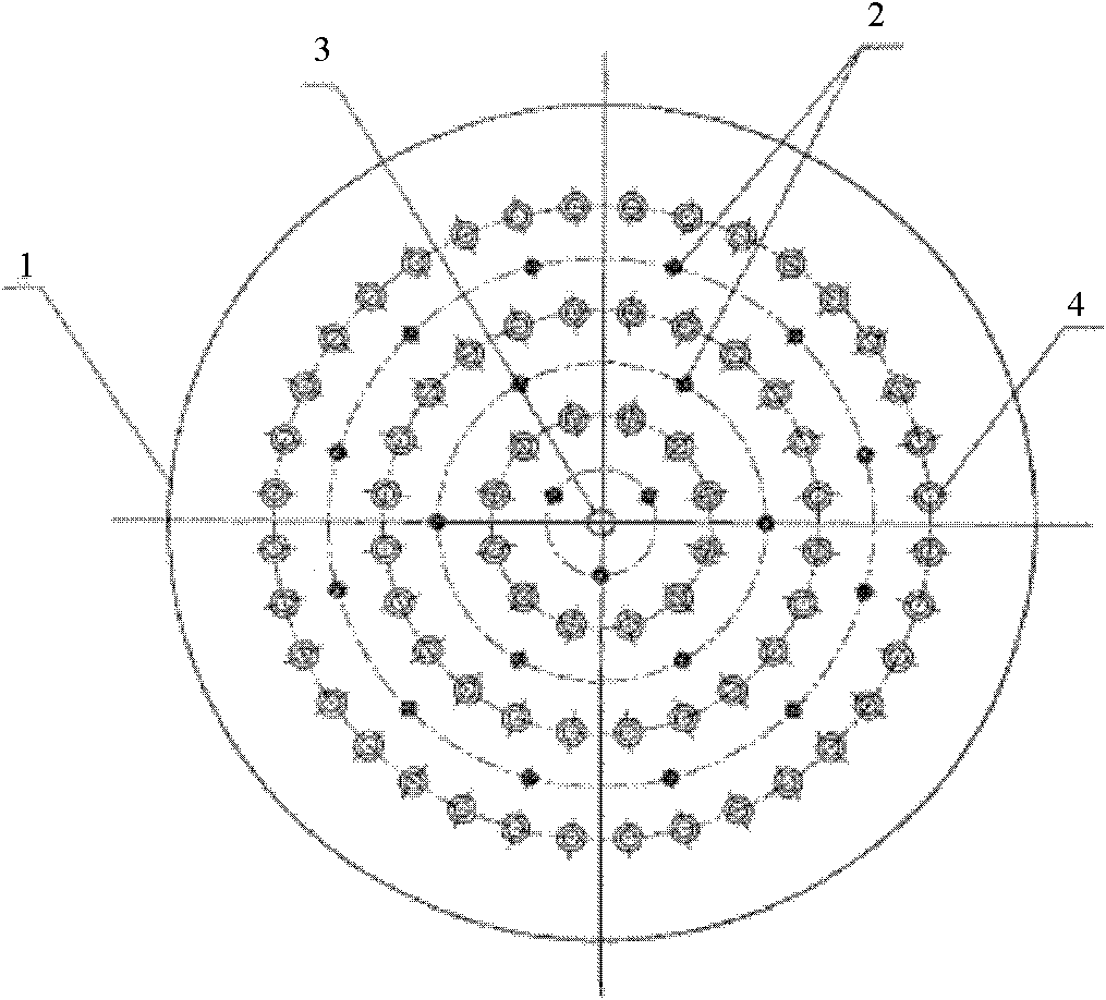
[0057] The arrangement of silicon cores in the polysilicon reduction furnace disclosed in this embodiment is different from that in the previous embodiment, as Figure 7-Figure 12 shown. The arrangement of the silicon cores in this embodiment is specifically as follows: taking the center of the chassis as the center of the circle, the area where the silicon cores are arranged is divided into three fan-shaped areas with an included angle of 120°, and the silicon cores in each fan-shaped area are arranged The way is symmetrical about the center of the chassis.
[0058] Among them, the above-mentioned arrangement can be divided into two categories. One is that as described in the previous embodiment, the six electrodes located at the center of the chassis are respectively connected to the electrodes of the outer layer, so that six electrodes are arranged at the center of the chassis. Silicon cores, the distribution of silicon cores in other areas depends on the number of silicon...
PUM
| Property | Measurement | Unit |
|---|---|---|
| Radius | aaaaa | aaaaa |
| Radius | aaaaa | aaaaa |
| Radius | aaaaa | aaaaa |
Abstract
Description
Claims
Application Information
 - R&D
- Intellectual Property
- Life Sciences
- Materials
- Tech Scout
- Unparalleled Data Quality
- Higher Quality Content
- 60% Fewer Hallucinations
Browse by: Latest US Patents, China's latest patents, Technical Efficacy Thesaurus, Application Domain, Technology Topic, Popular Technical Reports.
© 2025 PatSnap. All rights reserved.Legal|Privacy policy|Modern Slavery Act Transparency Statement|Sitemap|About US| Contact US: help@patsnap.com