Hydraulic self-elevating template for vertical shaft and construction method thereof

A formwork and vertical shaft technology, applied in the field preparation of formwork/formwork/work frame, building components, construction, etc., to achieve the effect of ensuring construction quality, high construction efficiency, and simple operation

Active Publication Date: 2012-10-03
CHINA GEZHOUBA GROUP CO LTD
View PDF3 Cites 17 Cited by
  • Summary
  • Abstract
  • Description
  • Claims
  • Application Information

AI Technical Summary

Problems solved by technology

[0002]In construction projects designed with shaft structures, the space of the shafts is often narrow and closed, which is not conducive to construction, especially for those using the usual The combination of small steel formwork and wooden formwork in bulk is very inconvenient for formwork installation, adjustment, concrete pouring, formwork removal, and formwork surface cleaning. The construction efficiency is low and the construction progress is slow; the construction quality is not easy to control, resulting in concrete The appearance quality is poor; at the same time, because there is no operating platform, it also affects safe production
[0003] Chinese patent CN202055516U discloses an integral formwork system for shaft lifting, which adopts a formwork system that can be recovered toward the axis center of the shaft. The problem is that the entire formwork system still needs It is difficult to ensure good position accuracy by using a crane to hoist in place, and it is very inconvenient to hoist for a shaft with a large height

Method used


Image

  • Hydraulic self-elevating template for vertical shaft and construction method thereof
  • Hydraulic self-elevating template for vertical shaft and construction method thereof
  • Hydraulic self-elevating template for vertical shaft and construction method thereof

Examples


Embodiment Construction

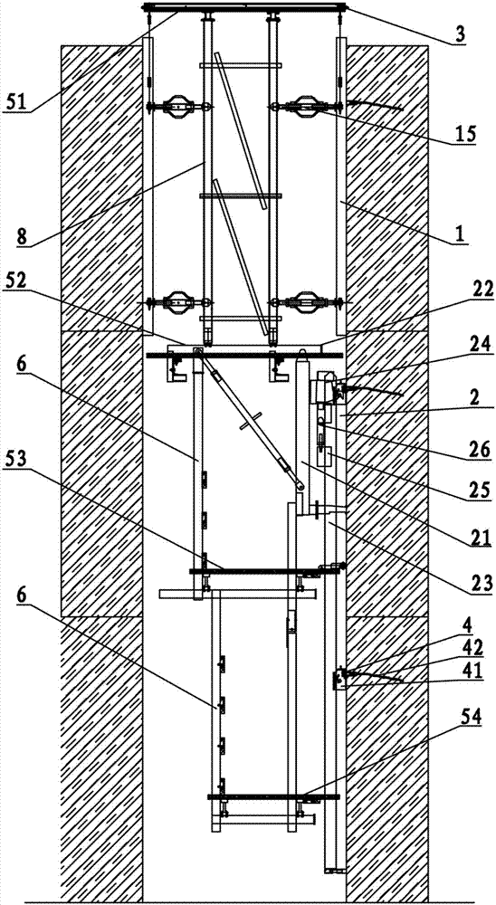
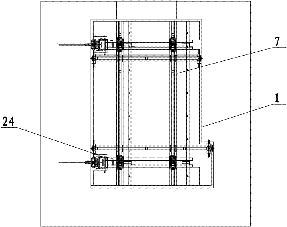
[0044] Such as figure 1 , image 3 Among them, a vertical shaft hydraulic self-elevating formwork, including a formwork device 1 for pouring the inner wall of the vertical shaft;

[0045] In the described formwork device 1, the plane formwork 11 is connected with the pole frame 8 through the formwork adjustment device 15. In this example, the formwork adjustment device 15 adopts a double-ended screw method, which can easily adjust the distance between the formwork and the pole frame 8. distance;

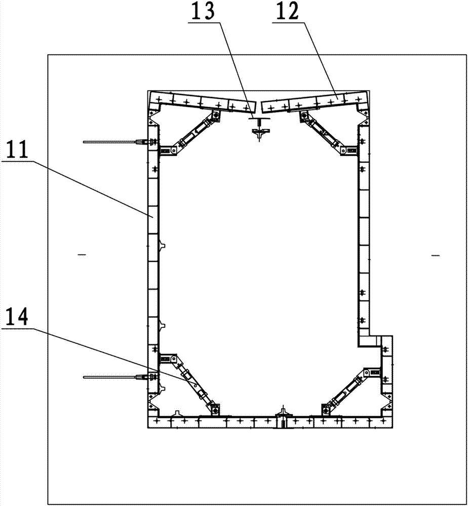
[0046] The two ends of the plane formwork 11 are connected to the corner formwork 12 through the diagonal support 14, and the two ends of the corner formwork 12 and the plane formwork 11 are hinged, and the two ends of the diagonal support 14 are respectively connected to the plane formwork 11 and the corner formwork 12, thereby by adjusting the The double-ended screw rod in the corner support 14 can make the corner formwork 12 rotate around the hinge point, so as to facilitate th...


PUM


Abstract

The invention discloses a hydraulic self-elevating template for a vertical shaft. The hydraulic self-elevating template comprises a template device, a mold withdrawal device, an anchoring device and a climbing frame device which is arranged below the template device and is used for climbing of a whole template assembly, wherein according to the climbing frame device, a plurality of climbing frame guide rails are connected with an anchor cone through a suspension shoe; the climbing frame is connected with the suspension shoe through a suspension box; one end of a hydraulic jack is connected with the suspension box, and the other end of the hydraulic jack is connected with a locking device; and the locking device is connected with the climbing frame guide rails. According to the hydraulic self-elevating template, the whole device can self climb in the vertical shaft so as to finish pouring, and the fit between the vertical shaft and a ground platform is reduced. The template device, the climbing frame device and a four-layer working platform form an integral system, under the action of power provided by the hydraulic jack, the integral system can self climb in the vertical shaft, and the template is easy and convenient to operate and high in construction efficiency; and therefore, the construction quality of concrete is guaranteed, and the construction safety is improved; and moreover, the hydraulic self-elevating template is suitable for construction of the vertical shaft in a high-depth concrete structure, and working conditions that the template is required to be transferred by a plurality of times.

Description

technical field [0001] The invention relates to the technical field of building engineering formwork, in particular to a hydraulic self-elevating formwork suitable for shaft construction and a construction method. Background technique [0002] In construction projects designed with shaft structures, the space of shafts is often relatively narrow and closed, which is not conducive to construction, especially for the usual combination of small steel formwork and wooden formwork in bulk. Formwork installation, adjustment, concrete pouring, formwork removal, and formwork surface cleaning are very inconvenient, resulting in low construction efficiency and slow construction progress; the construction quality is not easy to control, resulting in poor concrete appearance quality; at the same time, the absence of an operating platform also affects safe production. [0003] Chinese patent CN202055516U discloses an overall lifting formwork system for a shaft, which adopts a formwork ...

Claims


Application Information

Patent Timeline
Patent Type & Authority Applications(China)
IPC IPC(8): E04G11/28
Inventor 周厚贵戴志清孙昌忠刘晓华黄家权
Owner CHINA GEZHOUBA GROUP CO LTD
Why Eureka
Try Eureka