Wo2009055633

A technology for pipe joints and pipes, applied in the field of pipe joints, can solve the problems of ineffective locking and the inability of the locking piece to withstand the connecting end.

Active Publication Date: 2010-06-09
圣戈班穆松桥 +1
View PDF0 Cites 9 Cited by
  • Summary
  • Abstract
  • Description
  • Claims
  • Application Information

AI Technical Summary

Problems solved by technology

In addition, when the gap between the pipe members is large and the internal pressure is high, there is a danger that the lock cannot withstand the back pressure of the coupling end and thus returns completely, thus making the lock ineffective

Method used


Image

  • Wo2009055633
  • Wo2009055633
  • Wo2009055633

Examples


Embodiment Construction

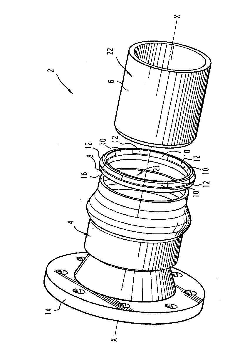
[0046] figure 1 A pipe connection according to the invention is shown, designated as a whole by the reference numeral 2 .

[0047] The pipe connection 2 has a first pipe part with a joint end 4 , a second pipe part with a coupling end 6 , a sealing ring 8 , an anti-extrusion part 10 and a locking part 12 .

[0048] The pipe joint 2 defines a central axis X-X. "Axial", "radial" and "circumferential" in the following description are all relative to the central axis X-X.

[0049] The engagement end 4 and the coupling end 6 are made of cast iron, for example. In addition, the piping members may be covered with a protective layer not shown.

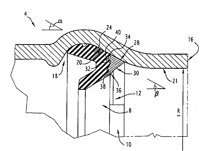
[0050] The joint end 4 has a fixed flange 14 for assembly with a pipe member (not shown) with a corresponding flange and a free end 16 facing the coupling end 6 in the unassembled state. The joint end 4 also has an annular inner groove 18 (see figure 2 ). Here, the inner groove 18 has a substantially circular cross-section, but other sh...


PUM


Abstract

The invention relates to a tubular connection comprising a joint end (4) comprising an inner groove (18) and having a plain end (6) inserted therein, a sealing jacket (8), and a locking member (12). The groove defines a groove wall (20). The plain end (6) and the joint end (4) define a radial gap (J). The locking member (12) includes a fixation tooth (36) and an application surface (28) for application against the wall (20) when the gap (J) is included in a first gap range. When the gap is included in a second gap range, the locking member (12) defines a tilting point (34) about the wall of the groove (20) and the fixation tooth (36) bites into the outer surface (22) through the arching of the locking member (12). Application in drinking water pipes.

Description

technical field [0001] The present invention relates to a pipe joint of the type comprising a joint end of a first pipe member extending along a central axis with an internal groove and a free end into which a coupling end of a second pipe member is inserted. In the free end, the inner groove forms a frusto-conical groove wall forming a first angle with the central axis and inclined relative to the central axis, narrowing towards the free end of the joint end, a sealing ring is located in the inner groove , at least one locking member is adapted to lock the coupling end relative to the joint end, a radial gap is defined between the coupling end and the joint end, and the gap may be within a first gap range or a second gap range, the second The gap in the second gap range is smaller than the gap in the first gap range. [0002] The invention is used in particular for conveying pipes for drinking water or sewage. Background technique [0003] Such pipe joints are known in th...

Claims


Application Information

Patent Timeline
Patent Type & Authority Applications(China)
IPC IPC(8): F16L37/08F16L21/08F16L37/084
CPCF16L37/0845F16L17/035F16L21/08
Inventor J-P·维泰尔P·勒纳尔D·格罗让
Owner 圣戈班穆松桥
Why Eureka
Try Eureka