Wire clamp and electronic device using same

A technology of electronic devices and wire clamps, which is applied to the circuit layout of supporting structures, pipes/pipe joints/fittings, pipe supports, etc., which can solve the problems of error-prone wire routing assembly methods, small effective range of wire clamps, and easy structure and function. Failure and other issues

Inactive Publication Date: 2014-01-22
AU OPTRONICS (SUZHOU) CORP LTD +1
View PDF4 Cites 0 Cited by
  • Summary
  • Abstract
  • Description
  • Claims
  • Application Information

AI Technical Summary

Problems solved by technology

[0005] However, if the assembler uses the above-mentioned first method to fix the wires, the complicated wire routing assembly method is not only prone to errors, but also increases the assembly man-hours and affects the assembly efficiency of the production line.
Moreover, the attachment method of double-sided tape and single-sided tape is also prone to the problem of poor attachment, which in turn leads to lower assembly quality
For the above-mentioned second method, although the clamp is integrally formed, it is more difficult to manufacture the locking end mold, and the size is not easy to control
If the molding is not in place, the structural function will easily fail
In addition, the cable clip generally has a long "tail", and the fixing point between the cable clip and the base (for example, the housing of the electronic device) is long, which is not beautiful and easily interferes with other structures, causing great damage to the overall space resources. big waste
Furthermore, the effective range of this wire clamp is small, and it is easy to loosen and fail.

Method used


Image

  • Wire clamp and electronic device using same
  • Wire clamp and electronic device using same
  • Wire clamp and electronic device using same

Examples


Embodiment Construction

[0052] A number of embodiments of the present invention will be disclosed in the following figures. For the sake of clarity, many practical details will be described together in the following description. It should be understood, however, that these practical details should not be used to limit the invention. That is, in some embodiments of the present invention, these practical details are unnecessary. In addition, for the sake of simplifying the drawings, some commonly used structures and components will be shown in a simple and schematic manner in the drawings.

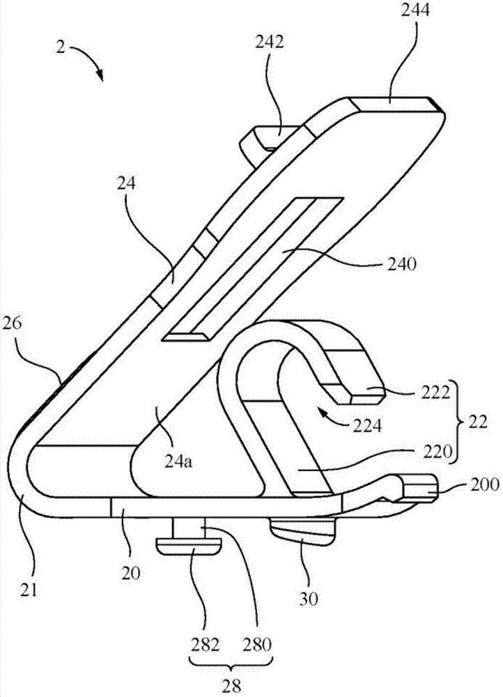
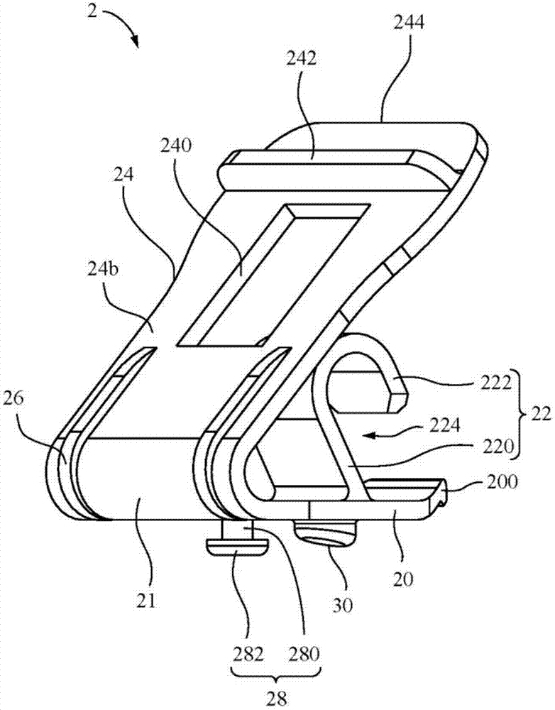
[0053] Please refer to Figure 1A as well as Figure 1B . Figure 1A A three-dimensional view of the cable clamp 2 according to an embodiment of the present invention is shown. Figure 1B draw Figure 1A Another perspective view of the wire clip 2 in .

[0054] Such as Figure 1A and Figure 1B As shown, in this embodiment, the wire clip 2 includes a main body 20 , a wire hook structure 22 and an elastic part 2...


PUM


Abstract

The invention provides a wire clamp and an electronic device using the wire clamp. The wire clamp is used for holding a wire. The wire clamp comprises a main body, a wire hook structure and an elastic sheet part, wherein the wire hook structure is connected with the main body, the elastic sheet part is connected with the main body and has a through-hole, and the elastic sheet part can be bended relative to the main body to move towards the main body, so as to allow the wire hook structure to partially pass through the through-hole. The wire is clamped between the elastic sheet part and the wire hook structure which partially passes through the through-hole. The wire clamp is mainly applied to the common wire arrangement as well as wire layout in electronic devices. The wire clamp has simple structure and low requirements for structure and material, therefore, the forming difficulty is low, the fabrication is facilitated and the occurrenceof structural function failures can be avoided mostly. The wire clamp provided by the invention can be used as a standard part.

Description

technical field [0001] The invention relates to a wire clip and an electronic device using the wire clip. Background technique [0002] In recent years, due to the rapid development of the electronics and information industries, their related products have become increasingly sophisticated. As far as the current personal computer field is concerned, in addition to seeking higher-speed, more computing-capable computing units and a variety of peripheral devices to meet the needs of users, it is also the development of the industry for thin, light and small portable computers. Important area. Taking liquid crystal display as an example, it has the advantages of high image quality, small size, light weight, low voltage drive, low power consumption and wide application range, so it is widely used in portable TVs, mobile phones, video recorders , notebook computers, desktop monitors and other consumer electronics products have become the mainstream of displays. [0003] On the ...

Claims


Application Information

Patent Timeline
Patent Type & Authority Patents(China)
IPC IPC(8): F16L3/06H05K7/02
Inventor 王伟程大伟李晓芳邱鹏严
Owner AU OPTRONICS (SUZHOU) CORP LTD
Why Eureka
Try Eureka