
In-place sensing device for workpiece inside furnace

A technology of induction device and workpiece, applied in furnace components, furnaces, lighting and heating equipment, etc., can solve the problems of production efficiency impact and high failure rate, achieve good protection, reduce impact force, and prevent frequent failure rates. Effect

Inactive Publication Date: 2012-10-03
苏州工业园区姑苏科技有限公司
View PDF5 Cites 4 Cited by
  • Summary
  • Abstract
  • Description
  • Claims
  • Application Information

AI Technical Summary

Problems solved by technology

[0002] The in-position detection of the workpiece in the furnace must pass through the induction device. Because the temperature in the furnace is high, the induction device cannot be installed in the furnace. The detection roller in the furnace is extended and extended to the outside of the furnace. A groove detection device is installed on the detection roller in the furnace. Then install a fixed plate on the end of the roller outside the furnace, and the travel switch is installed on the edge of the fixed plate. When the workpiece touches the detection plate in the furnace, the roller rotates, and the fixed plate outside the roller is driven to push the travel switch. After the travel switch receives the signal, it controls the rollers in the furnace to stop rotating. Since the fixed plate directly pushes the travel switch in this way, the failure rate is very high, and the travel switch must be replaced frequently; it will have a certain impact on production efficiency.

Method used


Image

  • In-place sensing device for workpiece inside furnace
  • In-place sensing device for workpiece inside furnace
  • In-place sensing device for workpiece inside furnace

Examples


Embodiment Construction

[0012] The present invention is described in detail below in conjunction with accompanying drawing and specific embodiment:

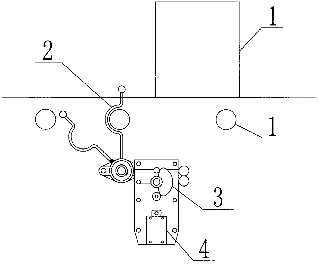
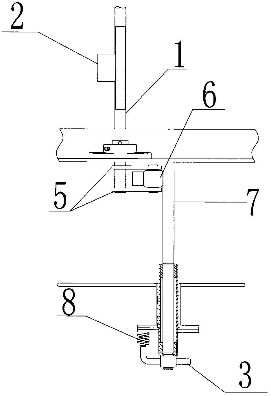
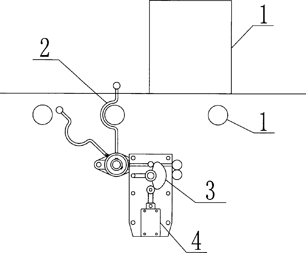
[0013] figure 1 , figure 2 The workpiece in-position sensing device in the furnace is shown, which includes a detection stick 1 connected to the inside and outside of the furnace body. The detection stick 1 in the furnace body is provided with a groove-type detection plate 2, and the end of the detection rod 1 outside the furnace is provided with a fixed plate. 5. A travel switch 4 is arranged on the side of the fixed plate 5; there are two fixed plates 5 on the end of the detection rod 1 outside the furnace, and a roller 6 is arranged between the two fixed plates 5; the roller 6 It is rollingly connected with one end of the detection shaft 7 arranged on its side, and the other end of the detection shaft 7 is provided with a cam type limit plate 3 capable of hitting the travel switch 4; the rear part of the cam type limit plate 3 is provided with a co...


PUM


Abstract

The invention relates to an in-place sensing device for a workpiece in a furnace. The in-place sensing device comprises a detecting stick, the inside of the furnace is communicated with the outside of the furnace via the detecting stick, a groove-shaped detecting plate is disposed on the detecting stick and positioned inside the furnace, two fixing plates are disposed at the end, which is positioned on the outside of the furnace, of the detecting stick, a travel switch is arranged on lateral edges of the fixing plates, a roller is arranged between the two fixing plates and is in rolling connection with one end of a detecting shaft disposed on a side surface of the roller, a cam type limiting plate capable of impacting the travel switch is arranged at the other end of the detecting shaft, and a return spring connected with the cam type limiting plate is arranged on the rear of the cam type limiting plate. The in-place sensing device for the workpiece inside the furnace has the advantages that the in-place sensing device is simple in structure, impact force on the travel switch is greatly reduced, an excellent protection effect for control of an integral system and service of the travel switch is realized, frequent failure is effectively prevented, maintenance cost is lowered, and production efficiency is improved.

Description

Technical field: [0001] The invention relates to an induction device, in particular to an induction device for workpiece position in a furnace. Background technique: [0002] The in-position detection of the workpiece in the furnace must pass through the induction device. Because the temperature in the furnace is high, the induction device cannot be installed in the furnace. The detection roller in the furnace is extended and extended to the outside of the furnace. A groove detection device is installed on the detection roller in the furnace. Then install a fixed plate on the end of the roller outside the furnace, and the travel switch is installed on the edge of the fixed plate. When the workpiece touches the detection plate in the furnace, the roller rotates, and the fixed plate outside the roller is driven to push the travel switch. After the travel switch receives the signal, it controls the rollers in the furnace to stop rotating. Since the fixed plate directly pushes t...

Claims


Application Information

Patent Timeline
Patent Type & Authority Applications(China)
IPC IPC(8): F27D21/00
Inventor 王彦荣钱林妹张文张海木
Owner 苏州工业园区姑苏科技有限公司
Learn More