Capillary tube flow testing device

A flow test device and capillary tube technology, which is applied in the direction of volume/mass flow generated by mechanical effects, fluid flow detection by measuring pressure difference, etc., can solve problems such as design errors and influences, and achieve the goal of improving authenticity and throttling effect Effect

Inactive Publication Date: 2012-10-03
LG ELECTRONICS (TIANJIN) APPLIANCES CO LTD
View PDF2 Cites 8 Cited by
  • Summary
  • Abstract
  • Description
  • Claims
  • Application Information

AI Technical Summary

Problems solved by technology

[0006] However, in the prior art, the throttling characteristics of the inner hole of the capillary are mostly used, and the intermediate pressure difference is read through the damping tube on the instrument and the measured capillary with a fixed inlet pressure to reflect the internal control resistance of the capillary of a certain length. The flow characteristics of the capillary can be judged within a short time, and the measurement results are completely within the tolerance range when the conventional flow monitoring is performed on the capillary with the same specification and different internal roughness, even if the change of the capillary roughness cannot be measured using the existing method, and For air conditioners, the roughness of the capillary is bound to have an impact on the refrigerant, which leads to a large error in the design

Method used


Image

  • Capillary tube flow testing device
  • Capillary tube flow testing device

Examples


Embodiment Construction

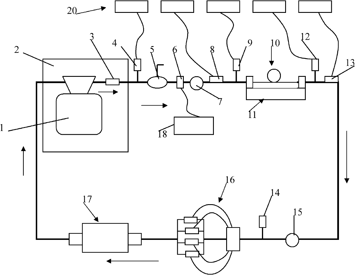
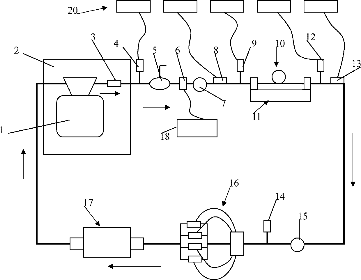
[0015] Below in conjunction with accompanying drawing and specific embodiment the present invention is described in further detail:

[0016] Such as figure 1 As shown, the capillary flow test device of the present invention includes: a refrigerant liquid storage tank 1 contained in a constant temperature box 2; a check valve 3 sequentially connected to the output port of the liquid storage tank 1 through a pipeline; The manual switch 4 at the rear of the one-way valve 3, the manual switch 4 can open or close the refrigerant flow path to start or terminate the flow test; the high-pressure regulator valve 7 connected in series behind the manual switch 4 in sequence; The capillary fixture 11 with the capillary 10 fixed; the inlet pressure sensor 9 and the outlet pressure sensor 12 respectively arranged in parallel on the refrigerant flow path near both ends of the capillary under test of the capillary fixture 11 ; Low-pressure stabilizing valve 15, self-balancing pressure contro...


PUM


Abstract

The invention discloses a capillary tube flow testing device, which comprises a refrigerant liquid storage tank, a one-way valve, a manual switch, a high pressure maintaining valve, a capillary tube clamp, an inlet pressure sensor, an outlet pressure sensor, a back pressure side lower pressure maintaining valve, a self-balancing type pressure control valve, a refrigerant recycling filling machine and a back pressure sensor. The refrigerant liquid storage tank is accommodated in a thermotank; the one-way valve is communicated with an output port end of the liquid storage tank via a pipeline; the manual switch and the high pressure maintaining valve are sequentially serially connected to the rear of the one-way valve; the capillary tube clamp is used for fixing a detected capillary tube; the inlet pressure sensor and the outlet pressure sensor are respectively parallelly connected to refrigerant flowing channels nearby two ends of the detected capillary tube fixed by the capillary tube clamp; the back pressure side low pressure maintaining valve, the self-balancing type pressure control valve and the refrigerant recycling filling machine are sequentially connected to the rear of the capillary tube clamp; and the back pressure sensor is parallelly connected to the rear of the low pressure maintaining valve. The capillary tube flow testing device forms a whole refrigerant loop and truthfully simulates the working state of the capillary tube, and calculates pressure difference of the refrigerant after the refrigerant passes through the capillary tube by controlling and measuring pressure and temperature, so that change of roughness of the capillary tube is detected, and the throttling effect of the capillary tube is improved according to the change.

Description

technical field [0001] The invention relates to the technical field of air conditioners, in particular to a test device for capillary flow of an air conditioner. Background technique [0002] An air conditioner is an electrical device that regulates and maintains the indoor temperature at the condition required by the user. The air conditioning function of the air conditioner is completed by the refrigeration circulation system and the air circulation system. The refrigerant circulating in the refrigeration system exchanges heat with the air flowing in the room to achieve indoor cooling or heating, and provide people with fresh and comfortable air. indoor air environment. [0003] The refrigerating cycle system of the air conditioner includes a heat exchanger, a compressor and throttling devices. The air circulation system includes a fan and a fan motor, an air inlet and outlet and an air filter. The operation of the refrigeration cycle system and the air cycle system of ...

Claims


Application Information

Patent Timeline
Patent Type & Authority Applications(China)
IPC IPC(8): G01F1/36
Inventor 杨瑱
Owner LG ELECTRONICS (TIANJIN) APPLIANCES CO LTD
Why Eureka
Try Eureka