Experiment device for simulating damage failure of conducting roller by work conditions

A technology for simulating material damage and working conditions, applied to measuring devices, analytical materials, instruments, etc., to achieve the effects of low manufacturing and operating costs, simple operation, and easy promotion

Inactive Publication Date: 2012-10-03
LICERAM ELECTRONICS TECH
View PDF2 Cites 4 Cited by
  • Summary
  • Abstract
  • Description
  • Claims
  • Application Information

AI Technical Summary

Problems solved by technology

[0005] The purpose of the present invention is to provide an experimental device for simulating the damage and failure of the conductive roller material under working conditions, so as to solve the technical problem that the existing experimental conditions for the damage and failure of the conductive roller material cannot truly reflect the failure behavior of the conductive roller material under actual working conditions

Method used


Image

  • Experiment device for simulating damage failure of conducting roller by work conditions
  • Experiment device for simulating damage failure of conducting roller by work conditions
  • Experiment device for simulating damage failure of conducting roller by work conditions

Examples


Embodiment Construction

[0023] The present invention will be described in detail below in conjunction with the accompanying drawings.

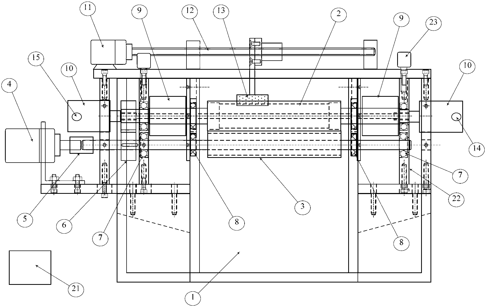
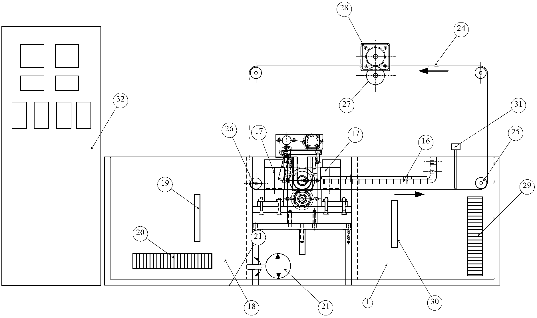
[0024] Please also see figure 1 and figure 2 , an experimental device for simulating the damage and failure of conductive roller materials under working conditions, including: a plating solution tank 1, an upper roller 2, a lower roller 3, a main drive speed regulating motor 4, a coupling 5, and upper and lower transmission gears 6 , a number of rolling bearings 7, sealing ring 8, collector ring 9, water cooling rotary joint 10, reversible motor 11, ball screw 12, upper roller grinding block 13, cooling water inlet 14, cooling water outlet 15, anode plate 16, conductive Carbon brush 17, preheating supply tank 18, preheating supply tank temperature sensor 19, preheating supply tank electric heater 20, liquid pump 21, bearing bracket 22, load regulator 23, endless strip steel 24, front guide roller 25, Rear guide roller 26, traction roller 27, strip steel driving mo...


PUM


Abstract

The invention discloses an experiment device for simulating the damage failure of a conducting roller by work conditions. The experiment device comprises a plating bath, bearing brackets arranged on two sides of the plating bath as well as an upper roller and a lower roller which are arranged in the plating bath, wherein two sides of the upper roller and the lower roller are respectively connected with the bearing bracket; the lower roller is connected with a driving speed regulating motor through a coupling; the upper roller and the lower roller are connected through an upper driving gear and a lower driving gear; rolling bearings connected with the upper and lower rollers are arranged in the bearing brackets; a collecting ring connected with the upper roller is arranged between the plating bath and the bearing bracket; water cooling rotary connectors are connected to two ends of the upper roller; an upper roller polishing block is also connected to the upper roller and is connected with a reversible motor through a ball screw; an anode plate and an upper conducting roller are arranged in the plating bath; and a preheating supplement groove is also arranged in one side of the plating bath. According to the experiment device disclosed by the invention, actual work conditions of the conducting roller can be simulated in multiple aspects; the simulation test for the damage failure of multiple conducting roller materials is developed; and a convenient and fast experiment method for developing new materials and processes is provided. In addition, the experiment device is simple and convenient in operation and easy for popularization.

Description

technical field [0001] The invention relates to an experimental device, in particular to an experimental device for simulating the damage and failure of conductive roller materials under working conditions. Background technique [0002] Conductor rolls are key components in continuous electroplating lines, transporting the steel strip and conducting the strong cathodic current during the electroplating process. Due to the harsh working conditions of the conductive roller, on the one hand, the conductive roller will contact the electroplating solution containing corrosive media such as hydrogen ions, sulfate ions, chloride ions, iron ions, etc. On the other hand, the surface of the conductive roller and the strip are constantly Friction causes wear. Therefore, in the actual use process, the surface quality of the conductive roller will deteriorate in a short period of time or even a short period of time (2 weeks to 2 months). etc.), which seriously affects the quality of el...

Claims


Application Information

Patent Timeline
Patent Type & Authority Applications(China)
IPC IPC(8): G01N3/00
Inventor 钟澄胡文彬刘磊沈彬
Owner LICERAM ELECTRONICS TECH
Why Eureka
Try Eureka