Electromagnetic environment automated testing device for aviational radio navigation station and method thereof

An aeronautical radio and automated testing technology, applied in the direction of electromagnetic field characteristics, can solve problems such as low measurement efficiency, many measurement items, and high labor intensity, and achieve the effects of enhancing accuracy and uniformity, improving measurement efficiency, and reducing labor intensity

Inactive Publication Date: 2012-10-03
ZHEJIANG MEASUREMENT SCI RES INST
View PDF1 Cites 12 Cited by
  • Summary
  • Abstract
  • Description
  • Claims
  • Application Information

AI Technical Summary

Problems solved by technology

[0002] GB6364-86 formulates the electromagnetic environment management of aeronautical radio navigation stations and the guidelines for electromagnetic compatibility between aeronautical navigation facilities and aeronautical radio navigation stations. There are no clear regulations on how to realize the test of the electromagnetic environment of aviation radio navigation stations, which brings difficulties to the accuracy and uniformity of the measurement.
At present, many domestic testing institutions have given measurement methods based on their own conditions according to the requirements of national standards and their own testing conditions. These measurement methods mainly have the following defects: (1) The equipment and methods are simple and scattered, and the standardization is poor; (2) Many manual operations and large human influence factors; (3) many measurement items and high labor intensity; (4) long measurement time and low measurement efficiency

Method used


Image

  • Electromagnetic environment automated testing device for aviational radio navigation station and method thereof
  • Electromagnetic environment automated testing device for aviational radio navigation station and method thereof

Examples


Embodiment Construction

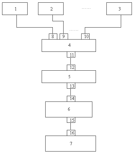
[0020] like figure 1 As shown, the electromagnetic environment automatic test device of the aviation radio navigation station includes the first antenna 1, the second antenna 2, the Nth antenna 3, the antenna switch 4, the filter 5, the spectrum analyzer 6, the computer 7, the first antenna switch Input port 8, second input port 9 of antenna switch, Nth input port 10 of antenna switch, output port 11 of antenna switch, filter input port 12, filter output port 13, spectrum analyzer signal input port 14, spectrum The GPIB data communication port 15 of the analyzer and the GPIB data communication port 16 of the computer; the antenna group is composed of the first antenna 1, the second antenna 2, and the Nth antenna 3 antennas, the first antenna 1 and the first input of the antenna switch Port 8 is connected, the second antenna 2 is connected with the second input port 9 of the antenna switch, the Nth antenna 3 is connected with the Nth input port 10 of the antenna switch, the fir...


PUM


Abstract

The invention discloses an electromagnetic environment automated testing device for an aviational radio navigation station and an electromagnetic environment automated testing method for the aviational radio navigation station. An antenna group consists of a plurality of antennas from the first to the Nth antennas which are respectively connected with input ports from the first to the Nth input ports of an antenna switch. The input ports from the first to the Nth input ports of the antenna switch are connected with the antenna switch respectively. The antenna switch, an antenna switch output port, a filter input port, a filter, a filter output port, a signal input port of a spectrum analyzer, a spectrum analyzer, a GPIB (General Purpose Interface Bus) data communication port of the spectrum analyzer, a GPIB data communication port of a computer and a computer are connected in sequence. According to the electromagnetic environment automated testing device for the aviational radio navigation station and the electromagnetic environment automated testing method for the aviational radio navigation station provided by the invention, the uncertainty and difference of test results among different test units in the test process are reduced, the accuracy and uniformity of measurement are ensured, thereby realizing the automated measurement, reducing the labor intensity, and improving the measuring efficiency tremendously.

Description

technical field [0001] The invention relates to the technical field of electronic measurement, in particular to an automatic test device and method for the electromagnetic environment of aviation radio navigation stations. Background technique [0002] GB6364-86 formulates the electromagnetic environment management of aeronautical radio navigation stations and the guidelines for electromagnetic compatibility between aeronautical navigation facilities and aeronautical radio navigation stations. For technical indicators such as strong signal value and its protection rate against interference from industrial, scientific and medical equipment, there are no clear regulations on how to test the electromagnetic environment of aeronautical radio navigation stations, which brings difficulties to the accuracy and uniformity of measurement. At present, many domestic testing institutions have given measurement methods based on their own conditions according to the requirements of nation...

Claims


Application Information

Patent Timeline
Patent Type & Authority Applications(China)
IPC IPC(8): G01R29/08
Inventor 陈习权孙杰朱中文顾夏珍韩海林陈婧
Owner ZHEJIANG MEASUREMENT SCI RES INST
Why Eureka
Try Eureka