Semiautomatic forming device for spring wire

A molding device and semi-automatic technology, applied in the direction of manufacturing extensible conductors/cables, etc., can solve the problems of long baking time, unfavorable energy saving, damage to the surface quality of spring wires, etc., to meet the requirements of assembly line production, simple and reasonable structure , The effect of saving power consumption

Active Publication Date: 2012-10-03
JIANGSU ZHONGLI GRP CO LTD
View PDF6 Cites 1 Cited by
  • Summary
  • Abstract
  • Description
  • Claims
  • Application Information

AI Technical Summary

Problems solved by technology

Not limited to the spring wire sizing devices disclosed in these two patents, there are the following disadvantages: first, since they all need to be baked in an oven to set the shape, there will be sticking, which will damage the surface quality of the spring wire; The time is lengthy, usually baked at a temperature of about 100-130 ° C for more than 30 minutes, which affects the setting efficiency; third, because the energy consumed by oven baking is large, it is not conducive to energy saving; fourth, oven baking is difficult or even impossible to meet Assembly line production requirements

Method used


Image

  • Semiautomatic forming device for spring wire
  • Semiautomatic forming device for spring wire
  • Semiautomatic forming device for spring wire

Examples


Embodiment Construction

[0018] In order to enable the examiners of the patent office, especially the public, to understand the technical essence and beneficial effects of the present invention more clearly, the applicant will describe in detail the following in the form of examples, but none of the descriptions to the examples is an explanation of the solutions of the present invention. Any equivalent transformation made according to the concept of the present invention which is merely formal but not substantive shall be regarded as the scope of the technical solution of the present invention.

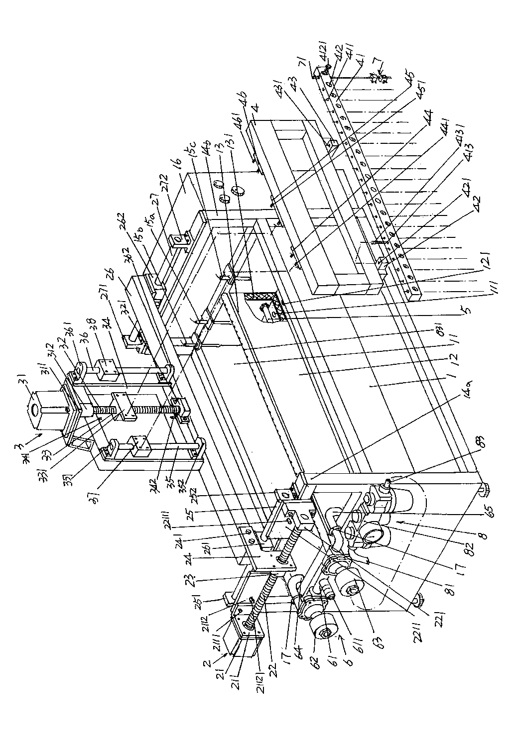
[0019] See figure 1 , provides a water tank 1, the length direction of the water tank 1 is divided into a hot water chamber 11 and a cold water chamber 12 by a heat insulation board 13, and a heat insulation layer 131 is provided in the interlayer of the heat insulation board 13, by the heat insulation layer 131 The heat insulation board 13 is made to exhibit an ideal heat insulation effect, and the mutu...


PUM


Abstract

The invention discloses a semiautomatic forming device for a spring wire, and belongs to the field of devices special for electric wire and cable machining. The semiautomatic forming device comprises a water tank, a horizontal movement mechanism, a hanging bar frame lifting mechanism, a hanging bar frame, a heater, a water supply mechanism and a group of spring wire clamping mechanisms, wherein the water tank is divided into a hot water chamber and a cold water chamber; the horizontal movement mechanism is arranged above the water tank; the hanging bar frame lifting mechanism is arranged on the horizontal movement mechanism; the hanging bar frame is provided with a spring wire clamping mechanism seat, and is arranged on the hanging bar frame lifting mechanism; the heater is arranged in the hot water chamber; the water supply mechanism is arranged on the water tank; each spring wire clamping mechanism comprises a hanging bar, a first wire clamping seat, a second wire clamping seat, a first wire pressing seat and a second wire pressing seat; the upper end of each hanging bar is connected with the spring wire clamping mechanism seat, and the lower end of the hanging bar forms a cantilever end; a first sliding hole is reserved in the center of each first wire clamping seat, and a first wire end embedding slot is reserved on one side of each first wire clamping seat; and a second sliding hole is reserved in the center of each second wire clamping seat, and a second wire end embedding slot is reserved on one side of each second wire clamping seat. The semiautomatic forming device has the advantages that the water tank is used for shaping the spring wire, so that quality can be ensured; shaping efficiency can be improved; power consumption can be reduced; the semiautomatic forming device is simple in structure; and a forming effect can be ensured.

Description

technical field [0001] The invention belongs to the technical field of special devices for wire and cable processing, and in particular relates to a spring wire semi-automatic forming device. Background technique [0002] Spring wire, also known as slingshot wire and helical wire, is a connecting wire that uses scalability to work. Because the spring wire not only has the advantages of ideal linear stability, excellent straightening and elastic height and elastic width, it is convenient for automatic winding, but also has outstanding fatigue resistance, flexibility and elasticity, so it is widely used. . Ordinary spring wires are used for the connecting wires between the handset of the telephone and the landline of the telephone set, the connecting wire of the walkie-talkie, the connecting wire between the power plug and the socket, etc.; Used in CNC machine tools, production lines, logistics systems, processing equipment, lifting equipment and industrial robots, etc.; mor...

Claims


Application Information

Patent Timeline
IPC IPC(8): H01B13/008
Inventor 孙建宇田飞叶烨朱冬琴杨利国张兴飞
Owner JIANGSU ZHONGLI GRP CO LTD
Why Eureka
Try Eureka