

Bridge type LC (inductance capacitance) resonance circuit with overcurrent protection function
A resonant circuit and overcurrent protection technology, applied in the direction of emergency protection circuit devices, electrical components, etc., can solve the problems of common and affecting circuit safety, etc., and achieve the effect of simple and clear principle, convenient application, and device solution
- Summary
- Abstract
- Description
- Claims
- Application Information
AI Technical Summary
Problems solved by technology
Method used
Image

Examples
Embodiment Construction
[0024] The following will clearly and completely describe the technical solutions in the embodiments of the present invention with reference to the accompanying drawings in the embodiments of the present invention. Obviously, the described embodiments are only some, not all, embodiments of the present invention. Based on the embodiments of the present invention, all other embodiments obtained by persons of ordinary skill in the art without creative efforts fall within the protection scope of the present invention.
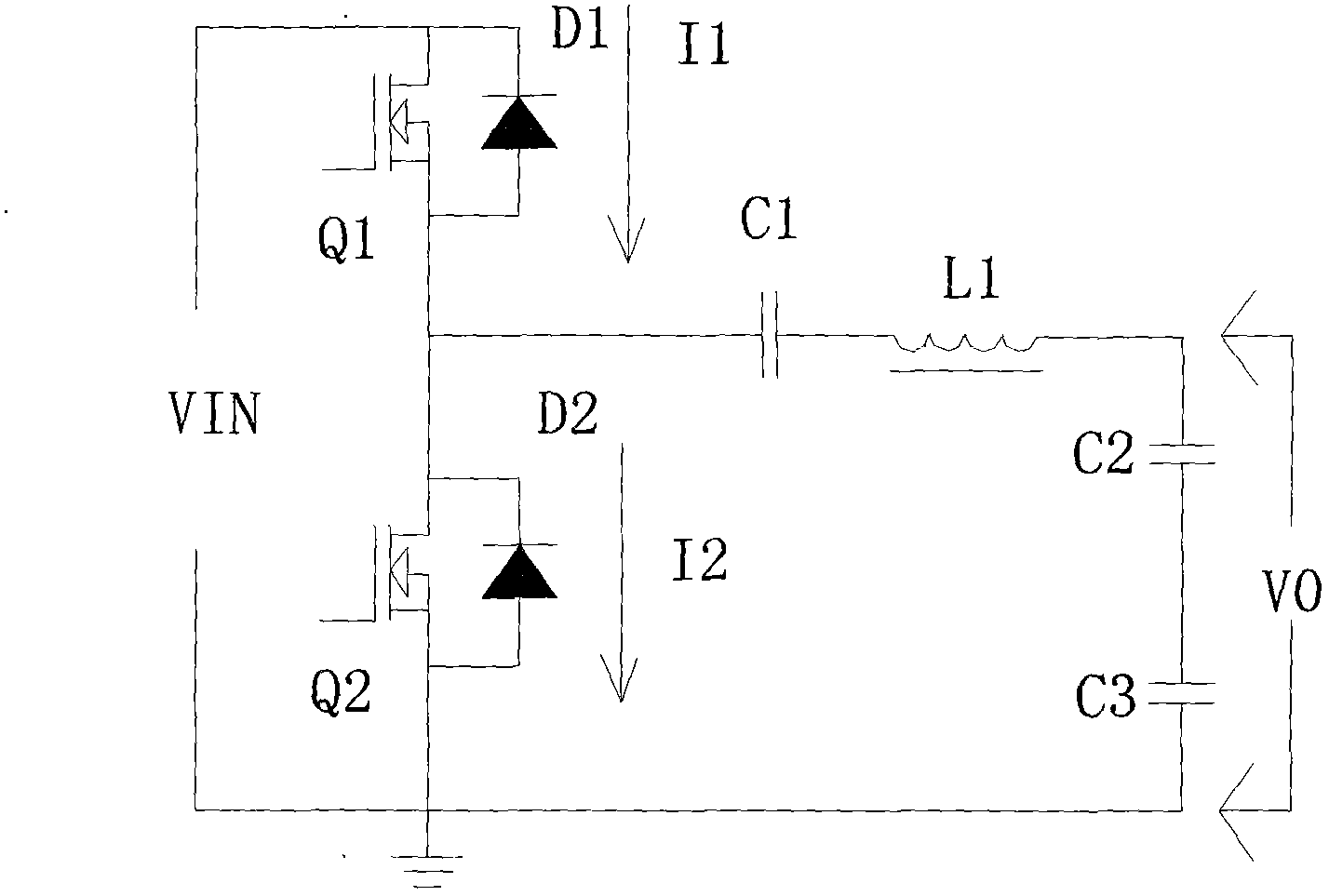
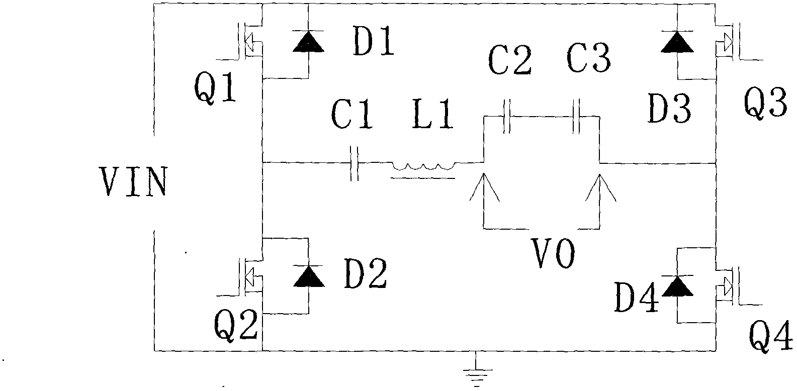
[0025] see figure 1 and figure 2 , the prior art resonant circuit of the present invention,
[0026] figure 1 It is a half-bridge structure, and the bus voltage utilization rate of this method is 50%. That is, VO≤0.5VIN
[0027] figure 2 It is a full-bridge structure, and the bus voltage utilization rate of this method is 100%. That is, VO≤VIN
[0028] When these two circuits work in a resonant state, the inductor L1\capacitor C1\capacitor C2\capacitor C3 ...
PUM
 Abstract
Description
Claims
Application Information