A bidirectional interface circuit

An interface circuit and interface technology, which is applied in the direction of logic circuit connection/interface layout, TV, electrical components, etc., can solve the problems that the interface circuit cannot be widely used in industrial sites, and the signal cannot be transmitted normally, so as to achieve a good synchronization effect and simplify the communication process. Effect

Active Publication Date: 2017-11-21
BEIJING DAHENG IMAGE VISION
View PDF4 Cites 0 Cited by
  • Summary
  • Abstract
  • Description
  • Claims
  • Application Information

AI Technical Summary

Problems solved by technology

according to figure 1 It can be seen that the opening and closing of the MOS tube is controlled by the first controller, so the MOS tube cannot be automatically protected according to the current flowing in the circuit
[0008] 2. The overcurrent protection switch tube is installed on the first controller end and is controlled by the first controller. The signal flow direction of the interface circuit is coordinated and controlled by the first controller and the second controller. If the two controllers do not cooperate OK, it will cause the signal to not be transmitted normally
Generally, the maximum voltage value that the IO pins of the controller can withstand will not exceed 5V, and the industrial site usually uses 24V DC power supply, so the usual interface circuit cannot be widely used in the industrial site

Method used


Image

  • A bidirectional interface circuit
  • A bidirectional interface circuit
  • A bidirectional interface circuit

Examples


Embodiment 1

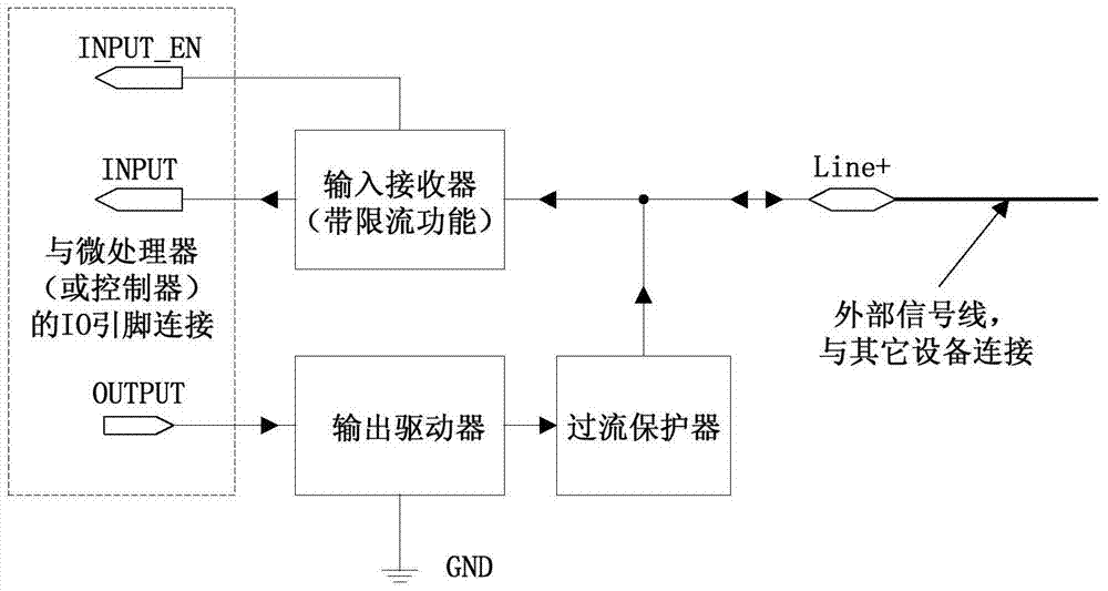
[0038] figure 2 and 3 A schematic block diagram and a circuit structure diagram of an embodiment of the present invention are shown respectively. like figure 2 As shown, in this embodiment, the bidirectional interface circuit is composed of an input receiver with a current limiting function, an output driver, an overcurrent protector, an INPUT pin, an INPUT_EN pin, an OUTPUT pin, a Line+ pin, and a GND pin .

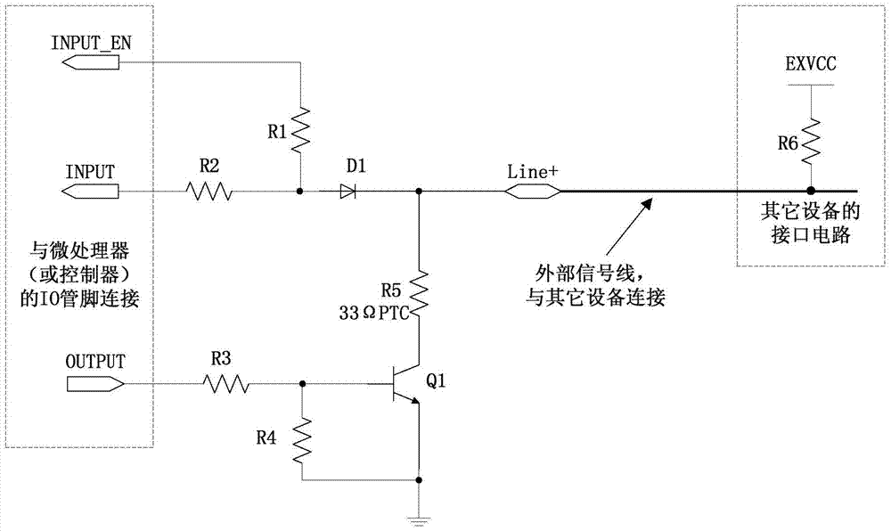
[0039] like image 3 As shown, the input receiver with current limiting function is composed of resistor R1, resistor R2, and Schottky diode D1; the output driver is composed of resistor R3, resistor R4, and NPN transistor (or NMOS) Q1; the overcurrent protector is composed of thermal Sensitive resistor R5 constitutes.

[0040] In this embodiment, the bidirectional interface circuit is used to connect the microprocessor of the industrial camera and the external device, such as the controller of the flashlight.

[0041] like image 3 As shown, the bidirectional i...

Embodiment 2

[0061] Figure 5A schematic block diagram of another embodiment of the invention is shown. In this embodiment, the INPUT_EN pin of the interface circuit is directly connected to the power supply VCCIO of the IO pin of the microprocessor (or controller). Once connected in this way, the input receiver does not need to be turned off. When the microcontroller sends data to the external signal line through the interface circuit, the input receiver will receive the data sent by the output driver, but this does not affect the work of the output driver, and can save the microprocessor (or controller) an IO pin. This scheme can be used when the IO pin resources of the microprocessor (or controller) are tight.

[0062] The bidirectional interface circuit of the present invention has an overcurrent protection function to prevent the interface circuit from being burnt out due to excessive input or output current; and it expands the IO level range of the internal microprocessor of the i...


PUM


Abstract

The invention provides a two-way interface circuit. The two-way interface circuit comprises an input interface, an input enable interface, an input receiver, an output interface, an output driver and an output overcurrent protector. The two-way interface circuit is capable of achieving two-way signal transmission by use of a single signal wire; the two-way interface circuit has an overcurrent protection function, and is capable of automatically detecting the current in the circuit and automatically opening the circuit for protection once the overcurrent phenomenon is found. After the fault is eliminated, the interface circuit automatically returns to work normally. In addition, the two-way interface circuit is capable of expanding the IO level range of an internal microprocessor of an industrial camera, so that the input / output level range can be 30V. The signal transmission time delay of the interface circuit is less than 5us, and is far less than the time delay within the range of 30 to 50us of an interface circuit formed by a photoelectric coupler. When the interface circuit is applied to the industrial camera, the control accuracy on relevant parts such as the camera and a flashlight can be remarkably improved, and therefore, the image pick-up and the gating of an external flashlight can be synchronized in a relatively good way.

Description

technical field [0001] The invention relates to the field of machine vision, in particular to a bidirectional interface circuit of an industrial camera used for machine vision detection. Background technique [0002] Machine vision systems have been widely used in production lines. As the "eyes" in the machine vision system, industrial cameras can be used to photograph the object under test, so that various aspects of the object under test can be detected. Through the IO interface of the industrial camera, you can control the shooting of the industrial camera, control the gating of the external light source, and communicate with other devices. [0003] In order to meet the protection of the microprocessor of the industrial camera, the existing IO interface circuit for the industrial camera is usually composed of a photocoupler, and the photocoupler can realize the isolation of the input signal from the input of the microprocessor. However, the delay time of the photocoupler...

Claims


Application Information

Patent Timeline
Patent Type & Authority Patents(China)
IPC IPC(8): H03K19/0175H04N5/77
Inventor 陆大伟仇开阳孙敬涛高原李永怀周中亚
Owner BEIJING DAHENG IMAGE VISION
Why Eureka
Try Eureka