
Four-quadrant multilevel current-source converter with main circuit based on thyristor

A current source type, thyristor technology, applied in the field of current source type switching converter topology, can solve the problems of phase current lag, abnormal operation of the device, restricting phase current lag phase voltage, etc. desired effect

Active Publication Date: 2012-10-03
内蒙古自治区电力科学研究院
View PDF0 Cites 9 Cited by
  • Summary
  • Abstract
  • Description
  • Claims
  • Application Information

AI Technical Summary

Problems solved by technology

[0002] Since thyristors have the highest power level in the family of power semiconductor devices, and the driving circuit is relatively simple, thyristor three-phase bridge circuits are widely used in high-voltage and high-power applications. However, since thyristors are semi-controlled devices, the gate trigger pulse can only Control its opening, so that the trigger angle phase shift range of the three-phase bridge is only 0~180°, which restricts its phase current to always lag behind the phase voltage, so the current source converter using the traditional thyristor three-phase bridge needs to be equipped with a considerable capacity The capacitor is used as a reactive power compensation device, which not only leads to an increase in the size of the device, but also capacitor failure is one of the main reasons for the device not working properly
[0003] In recent years, the application of voltage source converters based on fully-controlled devices IGBTs in the fields of light high-voltage direct current transmission and reactive power generators has gradually emerged, and the range of trigger angle phase shift of such devices has been extended to -180°~180°, Therefore, it is no longer necessary to configure additional inductors or capacitors for reactive power compensation. However, because the power level of the full-control device IGBT is significantly smaller than that of the thyristor, and the voltage source converter has poor short-circuit impact resistance, the converter based on this principle The operating performance in high-power occasions appears to be poor
[0004] Although there are currently two sets of twelve-pulse thyristor circuits in the form of three-phase bridges connected in parallel, which have been widely used in high-power applications, but because the angular phase shift range is still limited within the range of 0 to 180°, the control phase current always lags behind. The phase voltage problem still exists, and reactive power compensation has to be carried out to improve it. Can you explore a new method to make the thyristor commutate under the condition of zero current and realize controlled shutdown? The answer is feasible

Method used


Image

  • Four-quadrant multilevel current-source converter with main circuit based on thyristor
  • Four-quadrant multilevel current-source converter with main circuit based on thyristor
  • Four-quadrant multilevel current-source converter with main circuit based on thyristor

Examples


Embodiment Construction

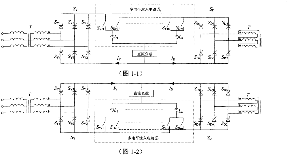
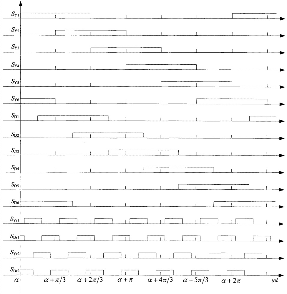
[0021] The main circuit is a thyristor-based four-quadrant multi-level current source converter, which is an AC-DC conversion circuit composed of a transformer, two sets of thyristor three-phase bridges combined in parallel and multi-level injection branches. The bridge thyristors provide zero-current commutation conditions and enable controlled turn-off of the thyristors. Depend on figure 1 As shown, it includes a transformer T, two sets of thyristor three-phase bridge S Y with S D , Multi-level harmonic injection circuit S r . Among them, the primary transformer T is three-phase, and the secondary includes two sets of windings: one set is Y-shaped connection, and the other is D-shaped connection. The transformation ratio of the primary winding to the secondary winding is k n : 1(Y) and Multi-level harmonic injection circuit S r for figure 1 The part of the dotted line in the middle is composed of multiple injection units with the same structure, and each group of inj...


PUM


Abstract

The invention relates to alternating-current to direct-current conversion of electric energy, discloses a four-quadrant multilevel current-source converter with a main circuit based on a thyristor and belongs to improvement to the fact that reactive power compensation is needed to be performed additionally caused by the fact that phase current is restricted and phase voltage is delayed due to a phase shift range of a trigger angle ranging from 0 to 180 when two groups of three-phase bridge-paralleled twelve-pulse thyristor circuits are utilized in high-power places. The converter is characterized in that a paralleling reactor in the topology is replaced by a multilevel injection circuit to enable each group of the three-phase bridges to output stepped multilevel pulse direct current and provide zero-current phase-commutation conditions for the thyristor. The multilevel injection circuit consists of multiple units with the same structure, each unit consists of two components with inverse resistant characteristics and a reactor, and cathodes or anodes of the components are connected with a terminal of the reactor to enable each group to structurally be a three-port unit. Consequently, the multilevel injection circuit and the main circuit are coordinated for controlling to provide the zero-current phase-commutation conditions for a main bridge thyristor, so that controlled turn-off of the thyristor is realized, and the whole circuit can possess four-quadrant operating capability.

Description

technical field [0001] The invention relates to the field of electric energy AC-DC conversion, in particular to the topology of a thyristor-based current source switching converter in a main circuit. Background technique, [0002] Since thyristors have the highest power level in the family of power semiconductor devices, and the driving circuit is relatively simple, thyristor three-phase bridge circuits are widely used in high-voltage and high-power applications. However, since thyristors are semi-controlled devices, the gate trigger pulse can only Control its opening, so that the trigger angle phase shift range of the three-phase bridge is only 0~180°, which restricts its phase current to always lag behind the phase voltage, so the current source converter using the traditional thyristor three-phase bridge needs to be equipped with a considerable capacity The capacitor is used as a reactive power compensation device, which not only leads to an increase in the size of the de...

Claims


Application Information

Patent Timeline
Patent Type & Authority Applications(China)
IPC IPC(8): H02M7/162H02M1/14
Inventor 杨宝峰刘永和王树一尹柏清陶军赵桂廷
Owner 内蒙古自治区电力科学研究院
Learn More