Pseudo-sunlight irradiating apparatus

A technology for illuminating devices and sunlight, which is applied to lighting devices, fixed lighting devices, optics, etc., and can solve problems such as difficulty in uniform illumination

Inactive Publication Date: 2012-10-03
SHARP KK
View PDF6 Cites 5 Cited by
  • Summary
  • Abstract
  • Description
  • Claims
  • Application Information

AI Technical Summary

Problems solved by technology

However, since the simulated sunlight irradiation device is in the form of point or line light sources, it is very difficult to irradiate the entire surface (or the entire area) of the light receiving surface of a solar cell with a planar light receiving surface with uniform illuminance. questions like this

Method used


Image

  • Pseudo-sunlight irradiating apparatus
  • Pseudo-sunlight irradiating apparatus
  • Pseudo-sunlight irradiating apparatus

Examples


no. 1 approach

[0043] (Simulating the structure of the sunlight irradiation device 18)

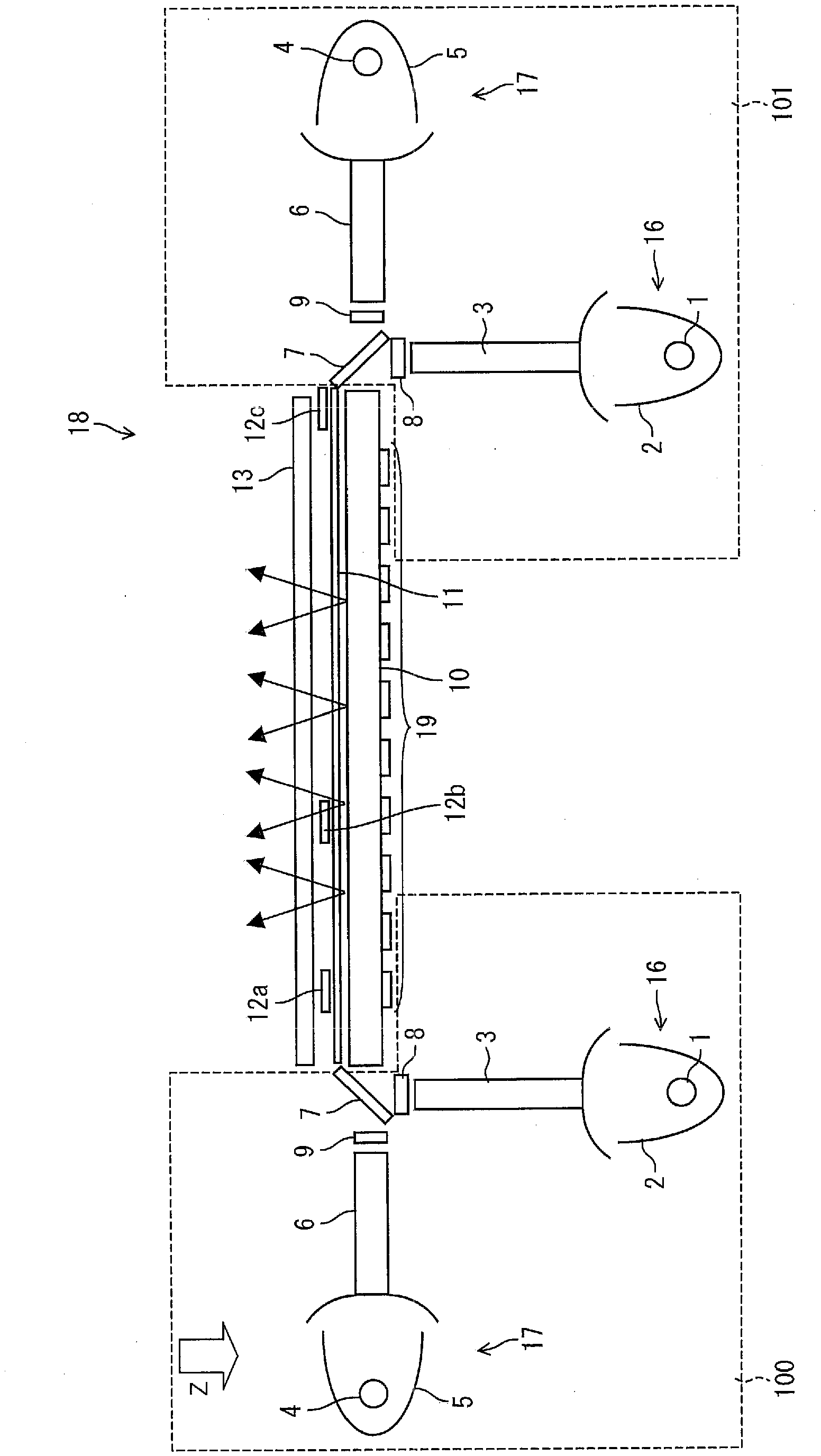
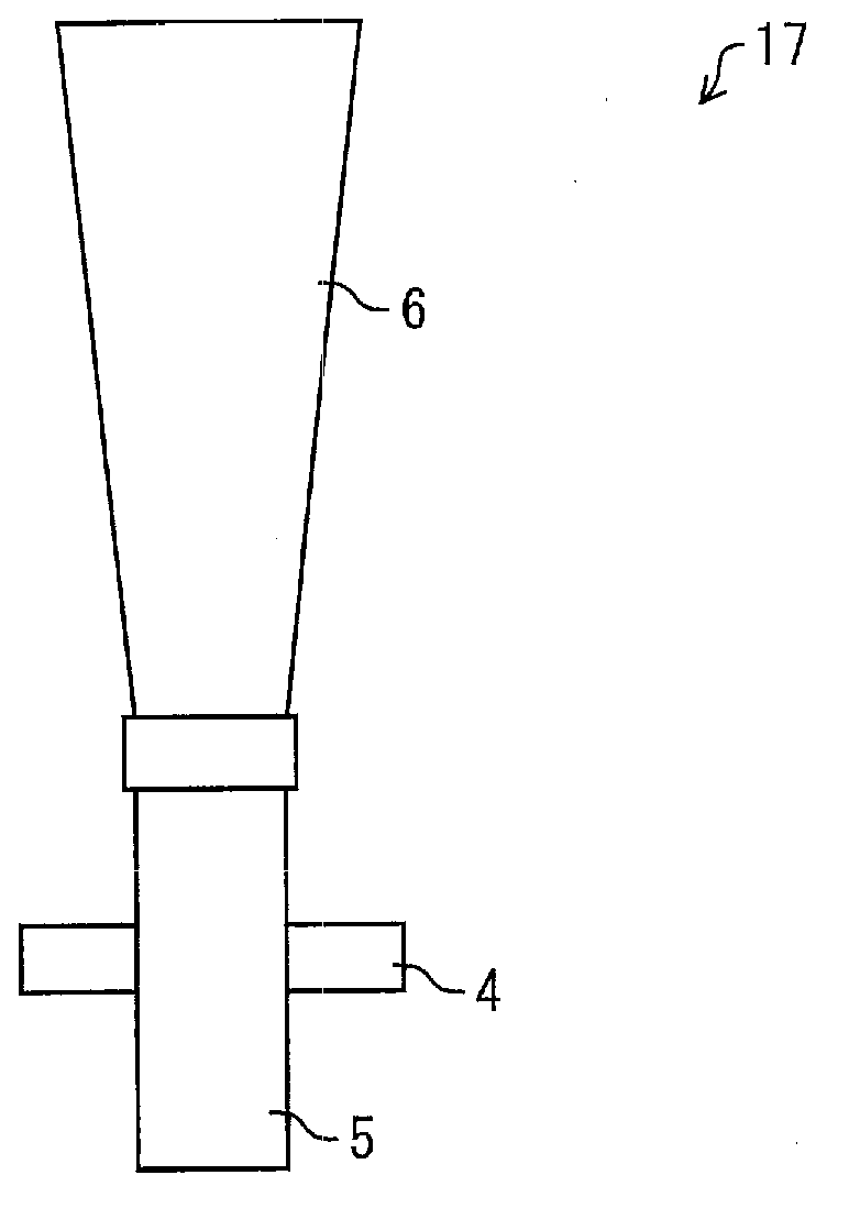
[0044] One embodiment of the present invention will be described with reference to the drawings. First, refer to figure 1 The simulated sunlight irradiation device 18 for irradiating simulated sunlight onto the irradiation surface 13 will be described in detail. figure 1 It is a figure which shows the structure of the main part of the simulated sunlight irradiation apparatus 18. As shown in FIG. Simulated sunlight is a type of artificial light that has a luminescence spectrum as similar as possible to that of natural light (sunlight). The pseudo-sunlight irradiation device 18 of the present embodiment can irradiate synthetic light of xenon light and halogen light as pseudo-sunlight. For example, a solar cell is arranged on the irradiation surface 13 .

[0045] like figure 1 As shown, the simulated sunlight irradiation device 18 includes: an optical package 100 , 101 composed of a xenon light source ...

no. 2 approach

[0087] (Simulating the structure of the sunlight irradiation device 38)

[0088] Another embodiment of the present invention will be described with reference to the drawings. In the simulated sunlight irradiation device of the present embodiment, the member for adjusting the illuminance is composed of two kinds of light transmittance adjusting sheets. Image 6 The structure of the main part of the pseudo sunlight irradiation device 38 of this embodiment is shown. like Image 6 As shown, the simulated sunlight irradiation device 38 includes: an optical package 100 , 101 composed of a xenon light source 16 and a halogen light source 17 , a light guide plate 10 and a prism sheet 11 . A light transmittance adjusting sheet (light transmittance adjusting member) 31 and a light transmittance adjusting sheet (light transmittance adjusting member) 32a formed on the light transmittance adjusting sheet 31 are provided on the side of the prism sheet 11 close to the irradiation surface 1...

no. 3 approach

[0104] (simulating the structure of the sunlight irradiation device 48)

[0105] Another embodiment of the present invention will be described with reference to the drawings. Although the number of the light transmittance adjustment sheets on the prism sheet 11 is small, it can reduce the number of components of the simulated sunlight irradiation device 18, 38 or shorten the distance between the irradiation surface 13 and the light transmittance adjustment sheet. more ideal. Therefore, in the simulated sunlight irradiation device of this embodiment, only one light transmittance adjustment sheet is provided. Figure 14 The structure of the main part of the pseudo sunlight irradiation device 48 of this embodiment is shown. like Figure 14 As shown, the simulated sunlight irradiation device 48 includes: an optical package 100 , 101 composed of a xenon light source 16 and a halogen light source 17 , a light guide plate 10 and a prism sheet 11 . A light transmittance adjusting ...


PUM


Abstract

A pseudo-sunlight irradiating apparatus (18) is provided with optical system sets (100, 101) each of which is comprised of a xenon light source (16) and a halogen light source (17), a light-guiding plate (10), and a prism sheet (11). Transmittance adjustment sheets (12a-12c) are formed on the prism sheet (11). The transmission rate adjustment sheets (12a-12c) has: a characteristic of letting most of the light having a wavelength shorter than a prescribed wavelength be transmitted therethrough, and reflecting most of the light having a wavelength longer than the prescribed wavelength; and / or a characteristic of reflecting most of the light having a wavelength shorter than a prescribed wavelength, and letting most of the light having a wavelength longer than the prescribed wavelength be transmitted therethrough. This enables transmittance of xenon light and transmittance of halogen light to be adjusted independently.

Description

technical field [0001] The invention relates to a simulated sunlight irradiation device for irradiating simulated sunlight on an irradiation surface. Background technique [0002] Demand for solar cells is increasing due to the recognition of their importance as a clean energy source. Solar cells are used in various fields ranging from power sources for large equipment to small power sources for precision electronic equipment. When solar cells are widely used in various fields, if the characteristics of the cells, especially the output characteristics, are not accurately measured, various failures can be expected on the side of using the solar cells. Therefore, there is particularly a need for a technology capable of irradiating a large area with high-precision simulated sunlight that can be used in inspection, measurement, and experiments of solar cells. [0003] Therefore, in recent years, a simulated sunlight irradiation device has been developed as a device capable of ...

Claims


Application Information

Patent Timeline
Patent Type & Authority Applications(China)
IPC IPC(8): F21S2/00H01L31/04F21Y101/00
CPCG02B6/0068G02B6/005G02B6/0028G02B6/007F21S8/006G02B6/0026
Inventor 南功治中村笃
Owner SHARP KK
Why Eureka
Try Eureka