Lighting apparatus
A technology for lighting devices and high-pressure discharge lamps, which is applied to projection devices, lighting devices, discharge lamps, etc., achieves a simple mechanism, suppresses uneven illumination distribution, and suppresses color unevenness.
- Summary
- Abstract
- Description
- Claims
- Application Information
AI Technical Summary
Problems solved by technology
Method used
Image
Examples
experiment example 1
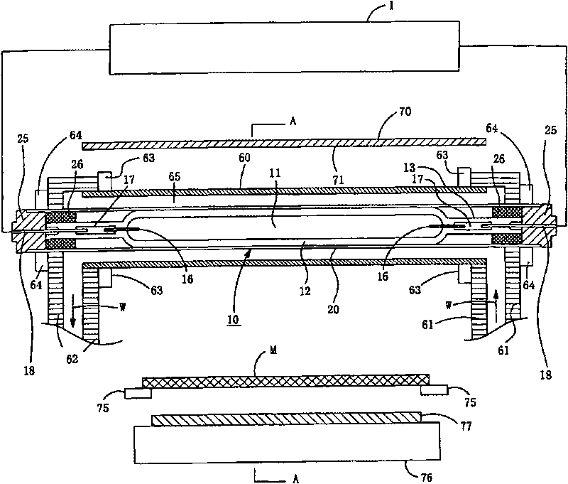
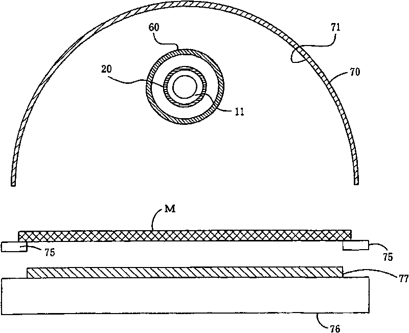
[0141] The configuration of the light irradiation device used in the experiment is shown in Figure 9 (a), having and expressing in the above figure 1 The light irradiation device has the same configuration, and its specifications are as follows.
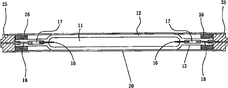
[0142] Discharge tube (light-emitting tube): inner diameter 5.4mm outer diameter 9mm
[0143] ·Outer tube: inner diameter 9.15mm outer diameter 12mm
[0144] ·Distance between electrodes: 500mm
[0145] ·Enclosure
[0146] Mercury density 5mg / cm 3
[0147] The flow rate of cooling water flowing between the water cooling jacket and the outer pipe: 20L / min
[0148] The lighting condition of the high-pressure discharge lamp used in the experiment is to input the stable lighting frequency f1 for 1 second, and then input the frequency f1 and f2 alternately in such a way that the low frequency f2 is input into the 1-cycle component (the opening and closing of the frequency f1 is regarded as 1 cycle). signal of. That is, the stead...
experiment example 2
[0164] The experiment was carried out under the same conditions as in Experimental Example 1 above, changing the light emitting length of the lamp (distance between electrodes) to 1000 mm. Lamp specifications are described below.
[0165] Discharge tube (light-emitting tube): inner diameter 5.4mm outer diameter 9mm
[0166] ·Outer tube: inner diameter 9.15mm outer diameter 12mm
[0167] Lighting length (distance between electrodes): 1000mm
[0168] ·Enclosure
[0169] Mercury density 5mg / cm 3
[0170] The flow rate of cooling water flowing between the water cooling jacket and the outer pipe: 25L / min
[0171] The results are shown in Table 2.
[0172] In this case, the frequency f1 is between 400 Hz and 500 Hz, and it can be seen that the suppression of unevenness in illuminance by acoustic resonance is effective.
[0173] Table 2
[0174]
[0175] (explanation of sign)
experiment example 3
[0177] The same experiment was performed under the same conditions as in Experimental Example 1 above, using a metal halide lamp with the lamp enclosure changed. Lamp specifications are described below.
[0178]Discharge tube (light-emitting tube): inner diameter 4.6mm outer diameter 10.3mm
[0179] ·Outer tube: inner diameter 10.45mm outer diameter 13mm
[0180] Lighting length (distance between electrodes): 500mm
[0181] ·Enclosure
[0182] Mercury density 2.5mg / cm 3
[0183] Iron iodide: 0.45mg / cm 3
[0184] Passive iodide: 0.06mg / cm 3
[0185] The flow rate of cooling water flowing between the water cooling jacket and the outer pipe: 20L / min
[0186] The results are shown in Table 3.
[0187] table 3
[0188]
[0189] (explanation of sign)
◎: Great effect
○: effective
△: some effect
×: almost no effect
[0190] In this case, the frequency f1 is between 1000 Hz and 1200 Hz, and it can be seen that the suppression of uneven...
PUM
| Property | Measurement | Unit |
|---|---|---|
| The inside diameter of | aaaaa | aaaaa |
| Outer diameter | aaaaa | aaaaa |
| Density | aaaaa | aaaaa |
Abstract
Description
Claims
Application Information
 - R&D
- Intellectual Property
- Life Sciences
- Materials
- Tech Scout
- Unparalleled Data Quality
- Higher Quality Content
- 60% Fewer Hallucinations
Browse by: Latest US Patents, China's latest patents, Technical Efficacy Thesaurus, Application Domain, Technology Topic, Popular Technical Reports.
© 2025 PatSnap. All rights reserved.Legal|Privacy policy|Modern Slavery Act Transparency Statement|Sitemap|About US| Contact US: help@patsnap.com


