Pouring system of motor relay casting technology

A casting process and sprue technology, which is applied in the field of motor casing casting process, can solve the problem of uneven density distribution and achieve the effect of reducing impact force

Inactive Publication Date: 2016-10-26
DALIAN JINHE CASTING
View PDF6 Cites 0 Cited by
  • Summary
  • Abstract
  • Description
  • Claims
  • Application Information

AI Technical Summary

Problems solved by technology

[0003] In view of the above-mentioned defects in the prior art, the present invention provides a pouring system for the motor relay casting process, which solves the problem of uneven density distribution caused by the gradual decrease in temperature when the molten iron rises from the bottom of the cavity

Method used


Image

  • Pouring system of motor relay casting technology
  • Pouring system of motor relay casting technology

Examples


Embodiment Construction

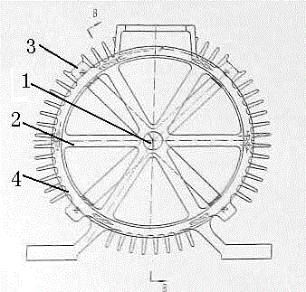
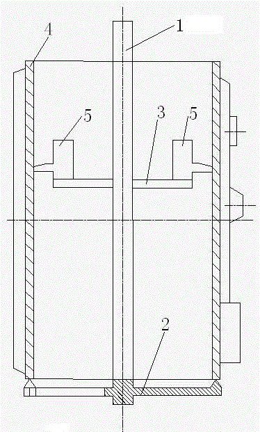
[0018] The pouring system of the motor relay casting process, its structure is as follows figure 1 As shown, it includes a longitudinal main runner 1, six horizontal bottom runners 2 and four horizontal relay runners 3; a longitudinal main runner 1 is set in the center of the cavity 4, and the longitudinal main runner 1 extends from the top of the cavity 4 to At the bottom of the cavity 4, one end of the longitudinal main runner 1 close to the bottom of the cavity 4 is connected to one end of the six horizontal runners, the other end of the six horizontal runners is connected to the bottom of the cavity, and the longitudinal main runner 1 is connected to four One end of a horizontal relay runner 3, and the other ends of the four horizontal relay runners 3 are connected to the cavity 4. A slag collecting bag 5 is arranged on the transverse relay runner 3 close to the cavity 4 , and the uppermost limit of the slag collecting bag 5 is higher than the uppermost limit of the transv...


PUM


Abstract

The invention belongs to the technical field of motor shell casting technologies, and particularly relates to a pouring system of a motor relay casting technology. The pouring system comprises a longitudinal main pouring gate, a plurality of transverse bottom pouring gates and a plurality of transverse relay pouring gates. The longitudinal main pouring gate is arranged in the center of a cavity and extends to the bottom of the cavity from the top of the cavity. The end, close to the bottom of the cavity, of the longitudinal main pouring gate is connected with one ends of the multiple transverse bottom pouring gates, and the other ends of the multiple transverse bottom pouring gates are connected to the bottom of the cavity. The longitudinal main pouring gate is connected with one ends of the multiple transverse relay pouring gates, and the other ends of the multiple transverse relay pouring gates are connected to the cavity. The pouring system solves the problem that when the molten iron ascends from the bottom of the cavity, due to gradual temperature reduction, density distribution is not even.

Description

technical field [0001] The invention belongs to the technical field of motor casing casting technology, and in particular relates to a pouring system for a motor relay casting technology. Background technique [0002] In the production of motor shells in the prior art, the traditional casting method adopts the process of bottom pouring with 6 runners. If a larger motor shell is processed, the temperature of molten iron entering the cavity from the 6 runners at the bottom will drop too much, which will easily lead to pouring The resulting shell has uneven density and poor quality. Contents of the invention [0003] In view of the above-mentioned defects in the prior art, the present invention provides a pouring system for the motor relay casting process, which solves the problem of uneven density distribution caused by the gradual decrease in temperature when the molten iron rises from the bottom of the cavity. [0004] In order to achieve the above purpose, the technical ...

Claims


Application Information

Patent Timeline
Patent Type & Authority Applications(China)
IPC IPC(8): B22C9/08B22C9/24
CPCB22C9/082B22C9/24
Inventor 马广华马作俊
Owner DALIAN JINHE CASTING
Why Eureka
Try Eureka