Light source unit using light emitting element

A light-emitting element and light source unit technology, which is applied to semiconductor devices, light sources, electric light sources, etc. Effects of suppressing the decrease of luminous intensity, increasing the contact area, and cooling with high uniformity

Active Publication Date: 2013-09-25
USHIO DENKI KK
View PDF2 Cites 0 Cited by
  • Summary
  • Abstract
  • Description
  • Claims
  • Application Information

AI Technical Summary

Problems solved by technology

[0008] That is, the flow path length of the flow path becomes longer, and the required flow rate of the cooling medium also increases, and the pressure loss increases accordingly, so it is difficult to circulate a necessary amount of cooling medium in the flow path, so the flow rate of the cooling medium becomes smaller. Less, with this, the contact area between the cooling medium and the heat sink becomes smaller and the LED element cannot be cooled sufficiently
[0009] In addition, in the flow path, the cooling medium has a large temperature difference between the upstream side and the downstream side, that is, a large temperature gradient occurs, so that a large number of LED elements cannot be cooled uniformly.

Method used


Image

  • Light source unit using light emitting element
  • Light source unit using light emitting element
  • Light source unit using light emitting element

Examples


experiment example 1

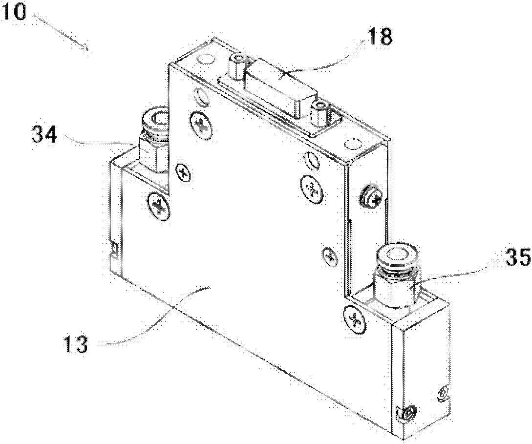
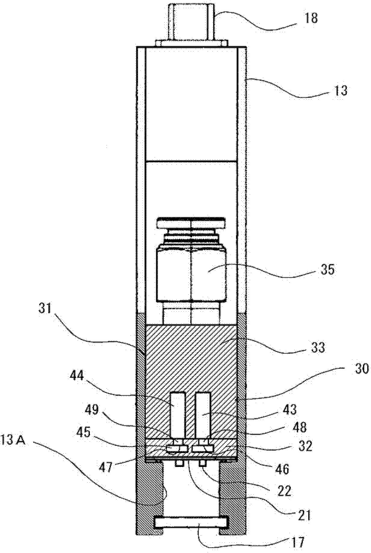
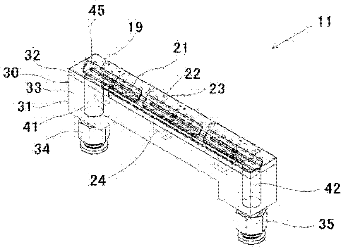
[0098] made with figure 1 A light-emitting element light source unit (hereinafter, also referred to as “light-emitting element light source unit ( 1 )”) having the structure of the example.

[0099] The substrate constituting the light-emitting element light source unit (1) is composed of 48 light-emitting parts composed of one LED element with a peak emission wavelength of 365nm arranged in two rows at a pitch of 4.6mm, with a width of 16mm, a length of 113mm, and a thickness of 0.6 mm. mm aluminum nitride construction.

[0100] In addition, the heat sink has a heat sink body made of copper, and has a circular cross-sectional shape (cross-sectional area of ​​12mm 2 ) supply path; the cross-sectional shape is a rectangular supply flow path with a width of 2.5mm and a height of 5mm; the cross-sectional shape is circular (the cross-sectional area is 3mm 2 ) inflow path; the cross-sectional shape is a rectangular cooling flow path with a width of 3mm and a height of 1mm; the c...


PUM


Abstract

Provided is a light source unit using light emitting elements, wherein the plurality of light emitting elements that comprise the light emitting source can be cooled efficiently, and with high uniformity, thereby enabling a decrease in light emitting intensity and any occurrence of illumination unevenness at the face to be illuminated, to be minimized. In the light source unit using light emitting elements, which comprises a heat sink upon which a plurality of light emitting units, each of which is comprised of one or more light emitting elements, are arranged at the top face thereof, the heat sink is provided with cooling flow paths, for letting cooling medium flow corresponding to one or a plurality of light emitting units, at an upper-face side level of the heat sink, and flow-in ports and flow-out ports for cooling medium provided within the cooling flow paths are connected to a supply flow path and a discharge flow path for cooling medium, formed at a level to the lower-face side of the heat sink than the cooling flow paths.

Description

technical field [0001] The present invention relates to a light-emitting element light source unit including a plurality of light-emitting parts composed of light-emitting elements such as LED (Light Emitting Diode) elements, and more specifically, to a light-emitting device that can be suitably used as light irradiation for fixing in a photocurable inkjet printer device. The light-emitting element light source unit used for the device. Background technique [0002] Recently, in photocurable inkjet printers, as a light irradiator for fixing, a light-emitting element such as an LED element is used as a light-emitting source (for example, refer to Patent Document 1). A light irradiator is generally configured by arranging a large number of LED elements at a high density in order to obtain a desired luminous intensity. [0003] However, in such a light irradiator for fixing, heat is generated as the LED elements emit light, and 80% to 90% of the input power is converted into h...

Claims


Application Information

Patent Timeline
Patent Type & Authority Patents(China)
IPC IPC(8): F21S2/00F21Y101/02
CPCF21Y2101/02F21V29/30F21Y2115/10F21V29/58F21V29/83
Inventor 中岛敏博村上悟司羽田博成片冈研
Owner USHIO DENKI KK
Why Eureka
Try Eureka