Wire rope flaw detection device

A flaw detection device and steel wire rope technology, applied in the direction of material magnetic variables, etc., can solve the problems of false detection signals generated by magnetic sensors, decreased detection sensitivity of damaged parts, and smaller, etc., to achieve the effect of reducing wear

Active Publication Date: 2012-10-03
MITSUBISHI ELECTRIC CORP
View PDF7 Cites 16 Cited by
  • Summary
  • Abstract
  • Description
  • Claims
  • Application Information

AI Technical Summary

Problems solved by technology

In addition, in Patent Document 2, there is a problem that the leakage magnetic flux density of the damaged part becomes smaller as the distance from the object to be inspected decreases. Therefore, when the distance between the object to be inspected and the magnetic sensor increases, the The detection sensitivity is lowered. In addition, if the distance from the magnetic sensor changes due to the vibration of the object to be inspected, a false detection signal will be generated in the magnetic sensor.

Method used


Image

  • Wire rope flaw detection device
  • Wire rope flaw detection device
  • Wire rope flaw detection device

Examples


Embodiment approach 1

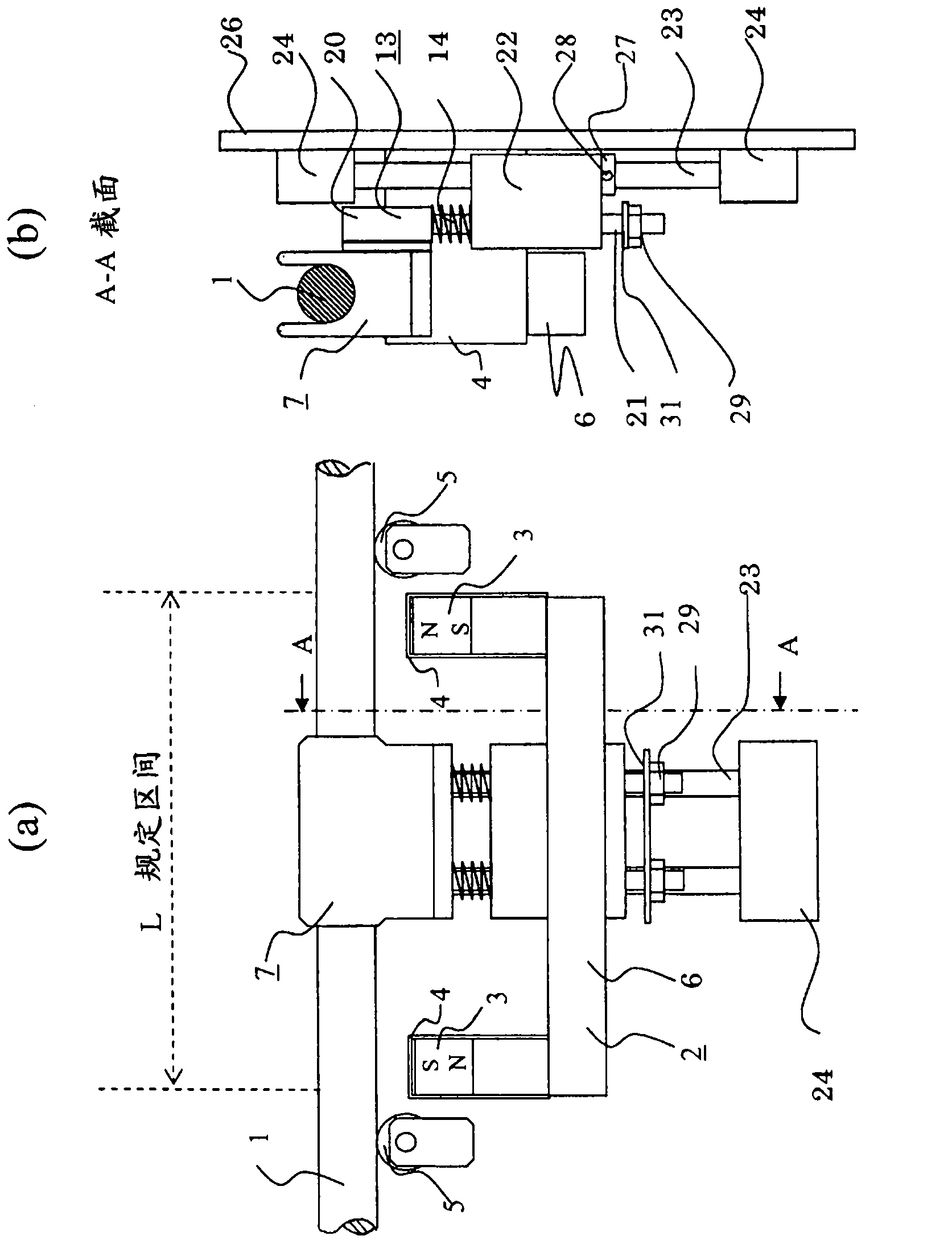
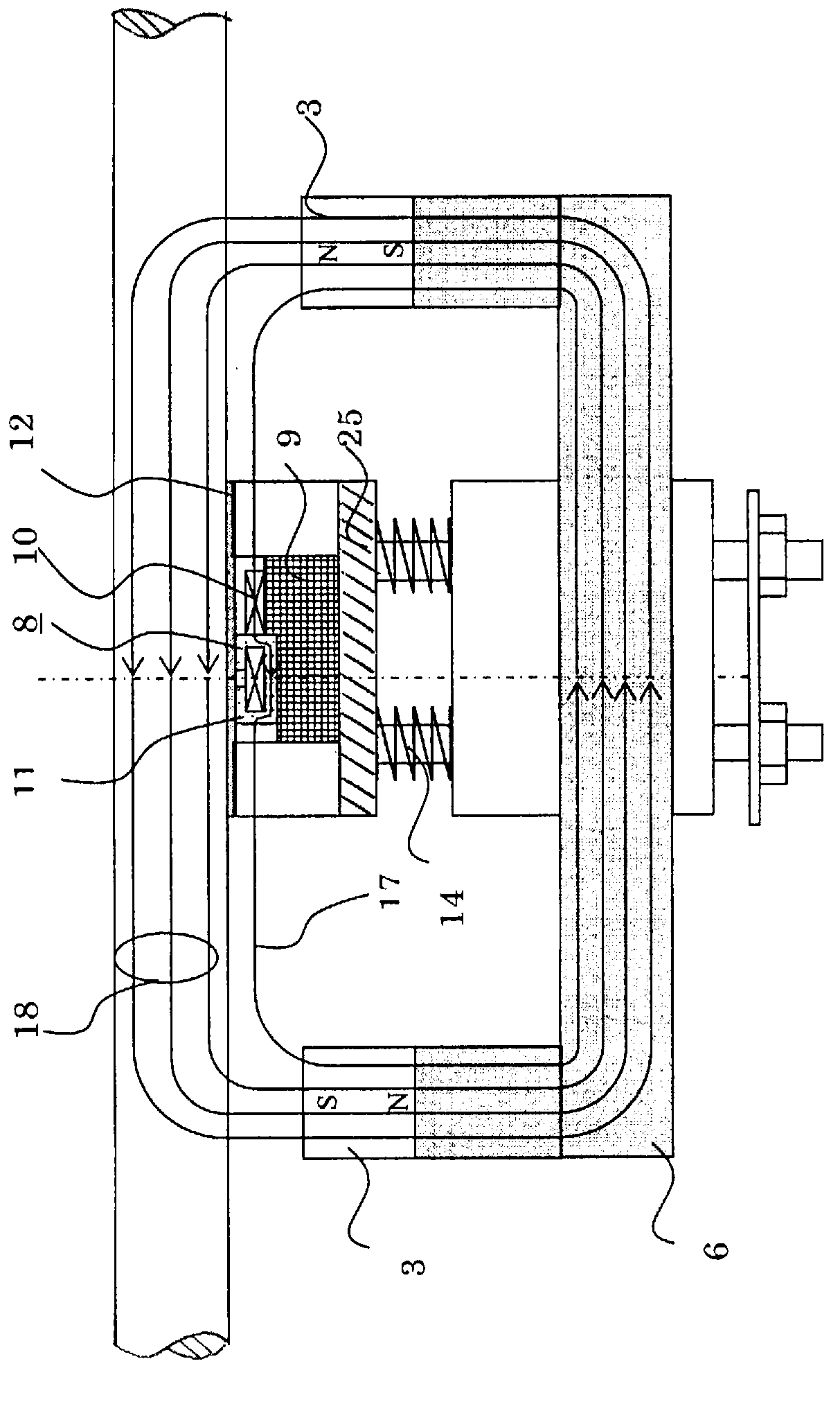
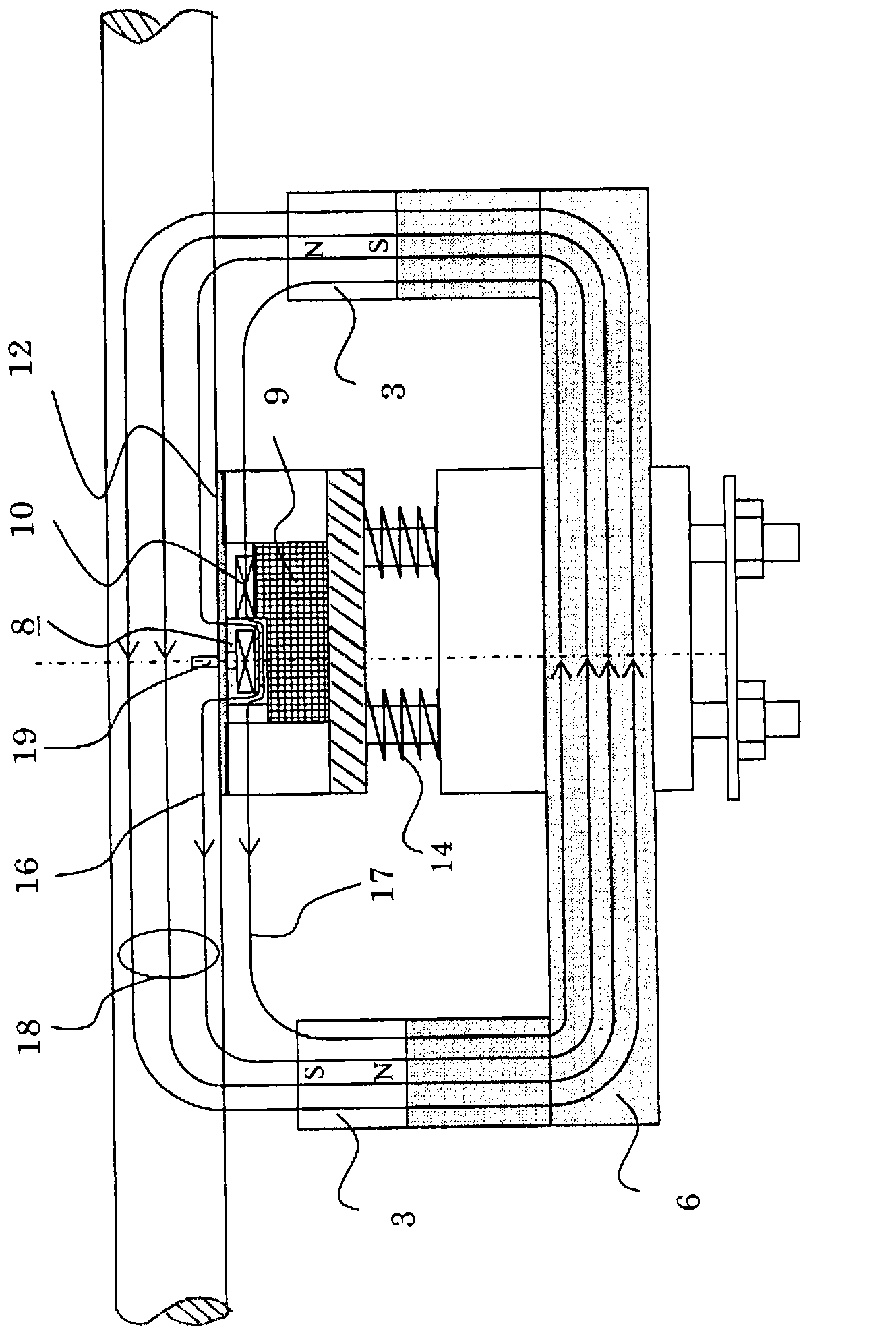
[0023] figure 1 It is a configuration diagram showing a wire rope flaw detection device according to Embodiment 1 of the present invention, figure 1 (a) is the front view, figure 1 (b) is the A-A line sectional view of (a). figure 2 It is an explanatory diagram showing the detection principle of the wire rope flaw detection device according to Embodiment 1, and shows a case where there is no damaged part of the wire rope. image 3 It is an explanatory diagram showing the detection principle of the wire rope flaw detection device according to the first embodiment, and shows a case where there is a damaged part of the wire rope. Figure 4 It is a perspective view of the wire rope flaw detection device of Embodiment 1. exist Figure 1 to Figure 4 In this case, the wire rope 1 is separated from the magnet cover 4 of the magnet 3 by a predetermined distance (for example, when the diameter of the wire rope 1 is 10 to 15 mm, it is about 5 to 10 mm), and the magnetizer 2 and the ...

Embodiment approach 2

[0034] Next, the wire rope flaw detection device according to Embodiment 2 will be described. Figure 5 It is a configuration diagram showing a wire rope flaw detection device according to Embodiment 2. Figure 6 It is a perspective view showing a wire rope flaw detection device according to Embodiment 2. Also, the same symbols in the drawings represent the same or corresponding parts. In Embodiment 2, two sets of components constituting the wire rope flaw detection device according to Embodiment 1 are respectively provided, and they are arranged in directions facing each other at 180° with respect to the wire rope 1 . A stopper 27 located near the end block 24 is slidable on the lower shaft 23 and fixed at a desired position.

[0035] By arranging two sets of magnetizers 2 in directions facing each other at 180° with respect to the wire rope 1, the uniformity of the magnetic flux distribution in the wire rope 1 increases. In Embodiment 2, the wire rope 1 is separated from ...


PUM

PropertyMeasurementUnit
diameteraaaaaaaaaa

Abstract

Provided is a wire rope flaw detection device, wherein the life of the device is extended without impairing the detection sensitivity and S / N of a wire rope damaged portion. Specifically provided is a wire rope flaw detection device for magnetizing a predetermined section in the axial direction of a wire rope (1) by a magnetizer (2) configured from a back yoke (6) and a magnet (3) and detecting a leakage magnetic flux generated from a wire rope damaged portion (19) in the predetermined section by a magnetic sensor (8) to thereby detect the wire rope damaged portion (19). The magnetizer (2) for magnetizing the wire rope (1) is disposed without being in contact with the wire rope (1), and the magnetic sensor (8) is disposed in contact with the wire rope (1) with a protection plate (12) interposed therebetween.

Description

technical field [0001] The present invention relates to a wire rope flaw detection device for detecting breakage of wire ropes used in elevators, construction cranes, etc., and strand breaks (hereinafter referred to as damaged parts of the wire rope). Background technique [0002] As such a wire rope flaw detection device, there is a device disclosed in Patent Document 1. This wire rope flaw detection device magnetizes the steel wire rope running at a certain speed by permanent magnets or electromagnets to a predetermined section in the axial direction of the steel rope, and detects the magnetic flux leaking from the damaged part of the steel wire rope by a magnetic sensor arranged in the predetermined section. . For this steel wire rope flaw detection device, the magnetic sensor for leakage flux detection and the magnetizer composed of a permanent magnet or electromagnet and a back yoke pass through a protective plate of non-magnetic material with a roughly U-shaped cross-...

Claims


Application Information

Patent Timeline
Patent Type & Authority Applications(China)
IPC IPC(8): G01N27/83
CPCG01N27/83G01N27/82
Inventor 吉冈孝笹井浩之宫本佳典
Owner MITSUBISHI ELECTRIC CORP
Why Eureka
Try Eureka