
Image processing device, image processing method, and program

A technology of image processing equipment and reference images, applied in image communication, television, electrical components, etc., can solve problems such as deterioration of coding efficiency, and achieve the effect of suppressing loss

Inactive Publication Date: 2012-10-03
SONY CORP
View PDF2 Cites 12 Cited by
  • Summary
  • Abstract
  • Description
  • Claims
  • Application Information

AI Technical Summary

Problems solved by technology

[0068] Although the above-mentioned AIF improves the performance of the interpolation filter, since the filter coefficient is included in the stream information, there is an overhead, and depending on the situation, it may occur that the encoding efficiency deteriorates

Method used


Image

  • Image processing device, image processing method, and program
  • Image processing device, image processing method, and program
  • Image processing device, image processing method, and program

Examples


no. 1 example

[0152] [Configuration example of image encoding device]

[0153] Figure 8 The configuration of the first embodiment of the image encoding device as the image processing device to which the present invention is applied is shown.

[0154] The image encoding device 51 compression-encodes an image input thereto, for example, based on the H.264 and MPEG-4 Part 10 (Advanced Video Coding) (hereinafter referred to as H.264 / AVC) method.

[0155] exist Figure 8 In the example of , the image coding device 51 is composed of the following parts: A / D converter 61, screen reordering buffer 62, arithmetic operation part 63, orthogonal transformation part 64, quantization part 65, lossless coding part 66, accumulation buffer 67. Dequantization section 68, inverse orthogonal transformation section 69, arithmetic operation section 70, deblocking filter 71, frame memory 72, switch 73, intra prediction section 74, motion prediction and compensation section 75, predicted image selection section...

no. 2 example

[0610] [Configuration example of image encoding device]

[0611] Figure 31 The configuration of the second embodiment of an image encoding device as an image processing device to which the present invention is applied is shown.

[0612] exist Figure 31 In the content shown, with Figure 8 Those components that are the same are indicated by like reference numerals. Duplicate descriptions are appropriately omitted.

[0613] Figure 31 The image encoding device 700 is configured with Figure 8 The difference in the configuration of the above is mainly that a motion prediction and compensation section 701 is provided instead of the motion prediction and compensation section 75 . The image encoding device 700 performs filtering processing on a reference image using SIFO (Single-Pass Switching Interpolation Filter with Offset).

[0614] It should be noted that SIFO is an intermediate interpolation filter between the fixed interpolation filter and AIF. Specifically, in SIFO...


PUM


Abstract

Disclosed are an image processing device, an image processing method, and a program, with which it is possible to inhibit the loss of high-frequency components and provide clear images. The disclosed selector (95) selects a filter coefficient from among the filter coefficient (A1) which is stored in the A1 filter coefficient memory (91) and used for all inter prediction modes when L0 / L1 weighted prediction is not employed, the filter coefficient (A2) which is stored in the A2 filter coefficient memory (92) and used for the bi-predictive mode when employing L0 / L1 weighted prediction, the filter coefficient (A3) which is stored in the A3 filter coefficient memory (93) and used for the direct mode when employing L0 / L1 weighted prediction, and the filter coefficient (A4) which is stored in the A4 filter coefficient memory (94),and used for the skip mode when employing L0 / L1 weighted prediction, and the selector outputs the selected filter coefficient to the fixed interpolation filter. The disclosed device and method can be applied to an image encoding device which performs encoding according to H.264 / AVC, for example.

Description

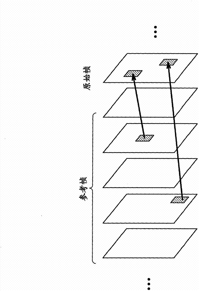
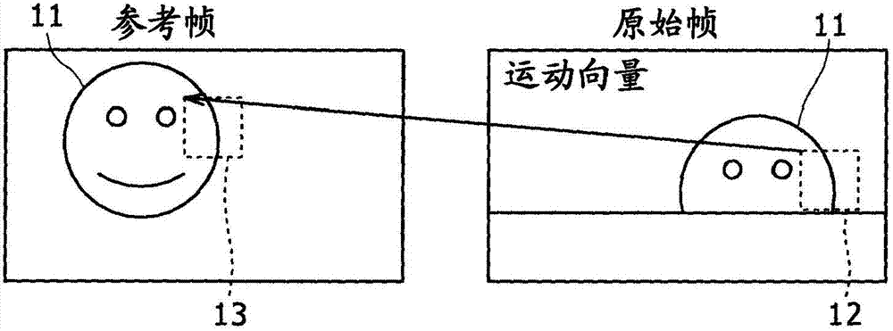
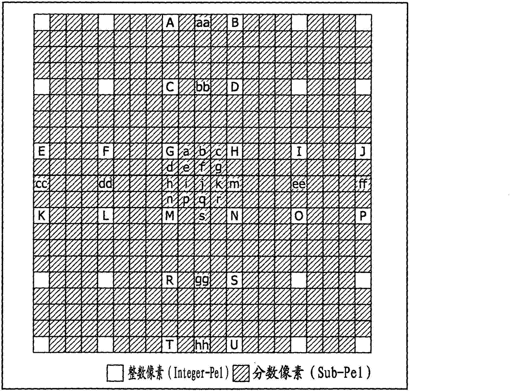
technical field [0001] The present invention relates to an image processing device and method, and in particular, to an image processing device and method capable of suppressing loss of high-frequency components and obtaining a clear sense of picture quality. Background technique [0002] As standard specifications for compressing image information, available are H.264 and MPEG-4 Part 10 (Advanced Video Coding, hereinafter referred to as H.264 / AVC). [0003] In H.264 / AVC, inter prediction focusing on the association between frames or fields is performed. Also, in the motion compensation process performed in interprediction, an interpredicted predicted image (hereinafter referred to as an interpredicted image) is generated using a part of an area of ​​an image that has been stored and can be referred to. [0004] For example, five frames in the image that have been stored and can be referred to are determined as reference frames (from figure 1 visible), a part of an interpr...

Claims


Application Information

Patent Timeline
Patent Type & Authority Applications(China)
IPC IPC(8): H04N7/32
CPCH04N19/00751H04N19/00127H04N19/00066H04N19/0089H04N19/117H04N19/132H04N19/587H04N19/80
Inventor 近藤健治
Owner SONY CORP
Learn More