Inverted punching and riveting machine and riveting method thereof

A technology of punching riveting machine and inverted type, which is applied in the field of improvement of inverted type punching riveting machine and its riveting method, which can solve the problems of affecting riveting quality, increasing labor intensity, and easy dislocation of riveting holes, etc., so as to simplify the structure and reduce labor intensity , The effect of improving processing efficiency

Inactive Publication Date: 2012-10-10
GUANGDONG MECHANICAL & ELECTRICAL COLLEGE
View PDF6 Cites 9 Cited by
  • Summary
  • Abstract
  • Description
  • Claims
  • Application Information

AI Technical Summary

Problems solved by technology

[0003] Most of the existing punching riveting machines are vertical punching riveting machines. The body of the vertical punching riveting machine is generally very large. Only one rivet can be punched; when multiple rivets are required to be riveted and fixed on the riveted part, it needs to be placed repeatedly, and the processing efficiency is low; and when one rivet is riveted, the other riveting holes are easy to be misplaced and need to be repositioned to further reduce the The processing efficiency is also affected, and the riveting quality is also affected; and the punching and riveting switch needs to be controlled manually, which increases the labor intensity; the open punching area has certain safety hazards
[0004] Therefore, the existing technology still needs to be improved and developed

Method used


Image

  • Inverted punching and riveting machine and riveting method thereof
  • Inverted punching and riveting machine and riveting method thereof
  • Inverted punching and riveting machine and riveting method thereof

Examples


Embodiment Construction

[0037] The specific embodiments of the present invention will be described in detail below in conjunction with the accompanying drawings, and the described specific embodiments are only used to explain the present invention, and are not intended to limit the specific embodiments of the present invention.

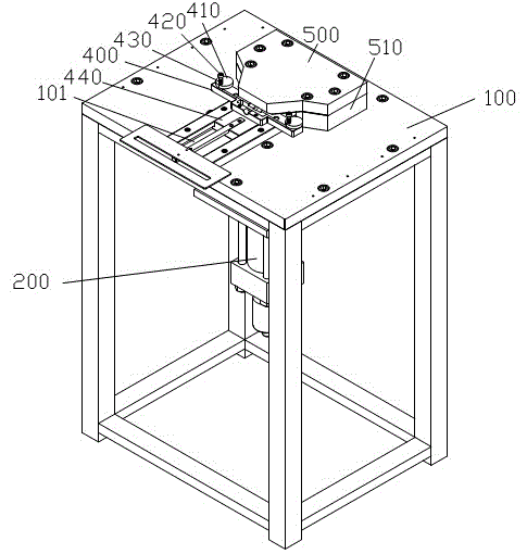
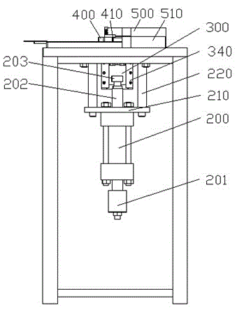
[0038] The invention discloses an inverted riveting machine. The inverted riveting machine is used to punch the bottom of the rivet of a workpiece to be riveted. Under the action of the punching force, the bottom of the rivet is deformed to form an undercut, thereby The workpieces to be riveted are riveted together. see figure 1 and figure 2 As shown, the punching riveting machine includes a workbench 100, a fixture 400 arranged on the workbench 100 for fixing the workpiece to be riveted, a punch 300 and an oil cylinder 200 arranged upside down on the workbench 100; The stamping force required by factors such as the quantity, structure, material and stamping deformation a...


PUM


Abstract

The invention discloses an inverted punching and riveting machine and a riveting method thereof. The punching and riveting machine comprises a worktable, a fixture, a punch and an oil cylinder, the punch consists of one or more than one punch needles, an upper die and a lower die, the punch and the oil cylinder are arranged on the lower side of the worktable in an inverted manner, a top plate, a slider and a sensing device with a magnet and a check block are disposed on the upper side of the worktable, the slider is used for mounting the fixture and is limited by the sensing device with the magnet and the check block, a pre-tightening device for tightening the fixture in advance is arranged on the punch, the oil cylinder is fixedly connected with the lower die, the punch needles penetrate through the upper die, and the lower end surface of each punch needle is abutted onto the lower die. The punch and the oil cylinder are arranged on the lower side of the worktable in the inverted manner, accordingly, the structure of the punching and riveting machine is compact and small, spaces are saved, the gravity center of the punching and riveting machine is low, a plurality of rivets can be simultaneously placed on workpieces to be riveted in advance and are punched to deform by the aid of the punch needles at one step, machining efficiency is greatly improved, and the rivets are impacted in a closed area and are quite safe.

Description

technical field [0001] The invention relates to the field of punching riveting machines, and more specifically, relates to an inverted punching riveting machine and an improved riveting method thereof. Background technique [0002] A rivet is a metal rod-shaped part with a cap on one end. After penetrating the components to be connected, the outer end of the rod is punched and pressed out to press and fix the components to be connected. There are many types of rivets, which can be divided into semi-round head, flat head and countersunk head rivets according to the structure of the rivet cap; according to the structure of the rivet shaft, it can be divided into semi-hollow, hollow, solid and blind rivets, etc. Riveting is divided into movable riveting and fixed riveting, and also divided into cold riveting and hot riveting. The general process is: drilling——inserting rivets——top mold against rivets——riveting into a cover shape. The application of rivets is very extensive. Co...

Claims


Application Information

Patent Timeline
Patent Type & Authority Applications(China)
IPC IPC(8): B21J15/10B21J15/20B21J15/28B21J15/30
Inventor 祝胜光
Owner GUANGDONG MECHANICAL & ELECTRICAL COLLEGE
Why Eureka
Try Eureka