All-lining debris flow draining and guiding groove with roughened groove bottom and application thereof

A technology for drainage channel and debris flow, which is applied in dikes, coastline protection, dams, etc., can solve the problems such as roughening of debris flow drainage channels that are not suitable for full lining, so as to save project operation and maintenance costs, reduce project maintenance costs, and improve The effect of roughness

Active Publication Date: 2012-10-10
INST OF MOUNTAIN HAZARDS & ENVIRONMENT CHINESE ACADEMY OF SCI
View PDF2 Cites 14 Cited by
  • Summary
  • Abstract
  • Description
  • Claims
  • Application Information

AI Technical Summary

Problems solved by technology

Therefore, the roughening method disclosed in the above invention patent can only work

Method used


Image

  • All-lining debris flow draining and guiding groove with roughened groove bottom and application thereof
  • All-lining debris flow draining and guiding groove with roughened groove bottom and application thereof
  • All-lining debris flow draining and guiding groove with roughened groove bottom and application thereof

Examples


Embodiment 1

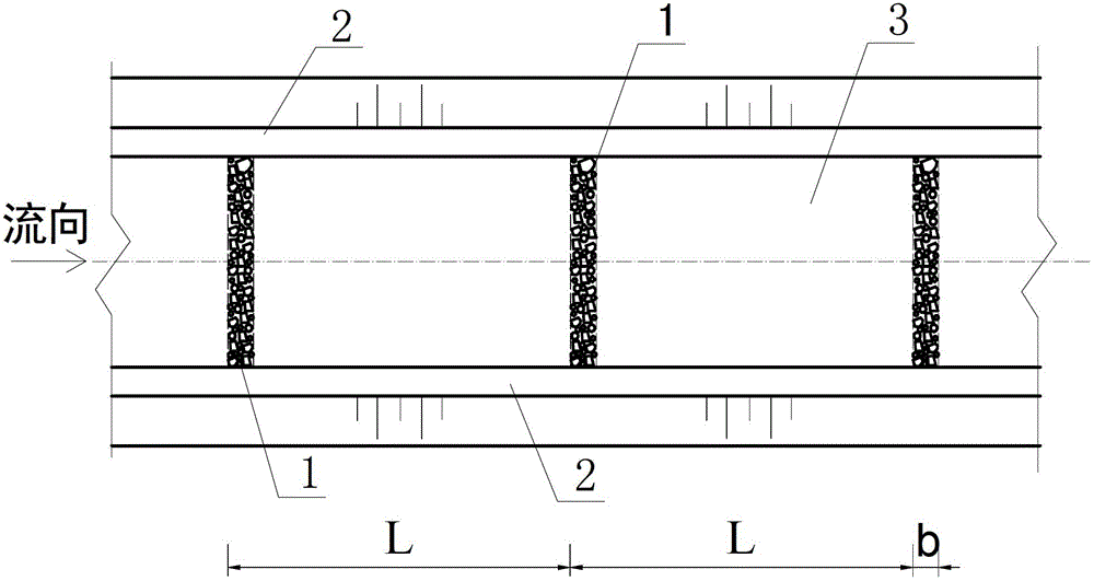
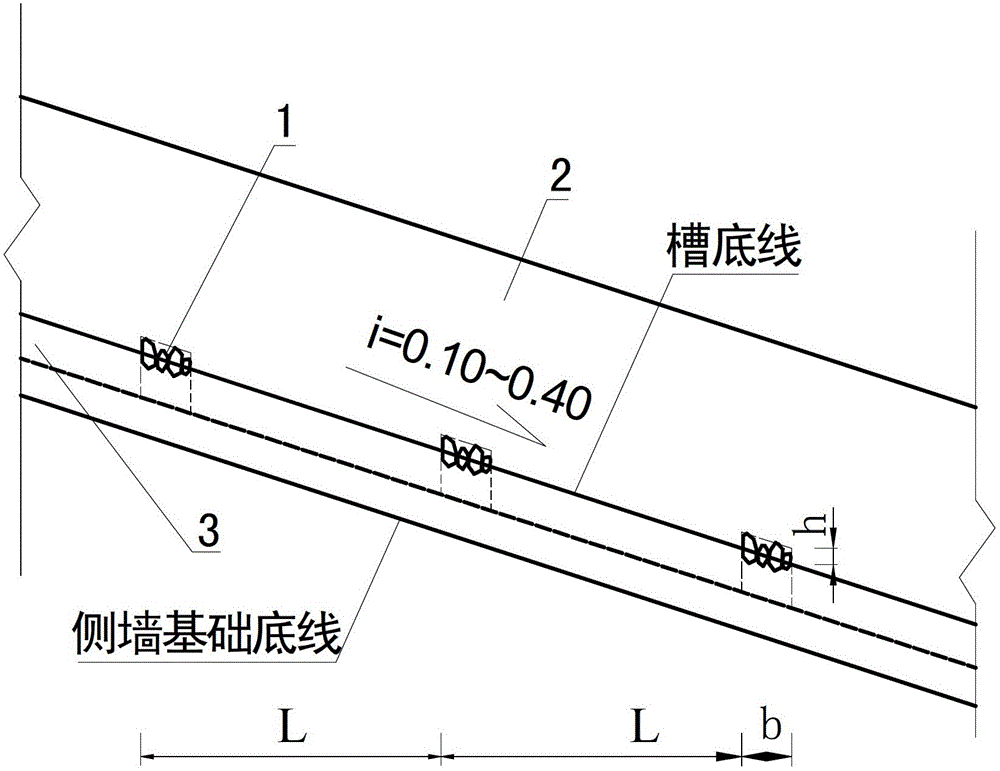
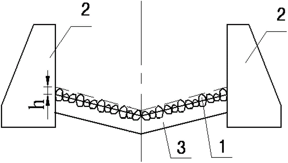
[0025] Such as figure 1 , figure 2 , image 3 shown. For a watershed area of ​​1.3km 2 , the slope of the accumulation fan is 40%, and the design flow rate of the once-in-20-year debris flow is 52m 3 / s, the density of debris flow is 20kN / m 3 , on the debris flow accumulation fan, build a fully lined debris flow drainage channel with a rough bottom, including a fully lined drainage channel bottom plate 3 and drainage channel side walls 2 on both sides. Above the bottom plate 3 of the guide groove, there are several roughened belts 1 that penetrate horizontally along the guide groove, are connected with the bottom plate 3 of the guide groove, are distributed at a certain distance, have a certain width and a convex height, and several roughened belts 1 with different convex heights. The roughened bodies are randomly arranged to form the roughened belt 1, and the top surface of the roughened belt 1 is uneven.

[0026] According to the slope of the accumulation fan, the ver...

Embodiment 2

[0029] Such as figure 1 , figure 2 , image 3 shown. For a basin area of ​​18.4km 2 , the slope of the accumulation fan is 10%, and the designed flow rate of debris flow once in 20 years is 126m 3 / s, the density of debris flow is 15kN / m 3 , on the debris flow accumulation fan, build a fully lined debris flow drainage channel with a rough bottom, including a fully lined drainage channel bottom plate 3 and drainage channel side walls 2 on both sides. Above the bottom plate 3 of the guide groove, there are several roughened belts 1 that penetrate horizontally along the guide groove, are connected with the bottom plate 3 of the guide groove, are distributed at a certain distance, have a certain width and a convex height, and several roughened belts 1 with different convex heights. The roughened bodies are randomly arranged to form the roughened belt 1, and the top surface of the roughened belt 1 is uneven.

[0030]According to the slope of the accumulation fan, the vertica...


PUM

PropertyMeasurementUnit
Spacingaaaaaaaaaa
Widthaaaaaaaaaa

Abstract

The invention discloses an all-lining debris flow draining and guiding groove with a roughened groove bottom and an application thereof. The draining and guiding groove comprises an all-lining bottom plate of the draining and guiding groove and side walls of the draining and guiding groove which are arranged at two sides. A plurality of roughened belts with a certain width and convex height are arranged above the bottom plate of the draining and guiding groove. The roughened belts transversely penetrate along the draining and guiding groove, are connected with the bottom plate of the draining and guiding groove and are distributed at a certain interval. A plurality of roughened bodies with different convex heights are distributed at random to constitute the roughened belts. The top surface of the roughened belts is uneven. Compared with the prior art, the draining and guiding groove provided by the invention fully utilizes the characteristic that the roughened belts can improve the roughness coefficient of the draining and guiding groove to reduce the flow speed of debris flow and then the abrasion kinetic energy of debris flow. Thus, the safety of the draining and guiding groove is greatly improved, the project maintenance cost is greatly lowered and the draining and guiding groove can well adapt to large-gradient longitudinal slopes of valleys. Compared with traditional draining and guiding grooves, the project operating maintenance cost can be saved by 50-80% by adding 2-5% of project investment and the project safety is greatly improved.

Description

technical field [0001] The invention relates to a mud-rock flow prevention technology, in particular to a fully-lined mud-rock flow drainage channel with a rough bottom and its application in the case of a valley with a large gradient. Background technique [0002] Debris flow disaster is one of the main types of geological disasters in my country. With the development of the mountainous area economy and the deepening of the western development, the demand for debris flow engineering is becoming more and more vigorous. The fully lined debris flow drainage channel is a common engineering measure for debris flow engineering. Will be heavily applied. [0003] Due to its much higher bulk density than water, debris flow has a special fluid structure containing clastic soil, so the movement of debris flow shows the characteristics of high inertia, strong transport force, huge impact force, strong abrasive force, etc. The bottom of the lining-type debris flow drainage channel is ...

Claims


Application Information

Patent Timeline
IPC IPC(8): E02B3/10
Inventor 陈晓清李德基游勇杨东旭
Owner INST OF MOUNTAIN HAZARDS & ENVIRONMENT CHINESE ACADEMY OF SCI
Why Eureka
Try Eureka