Motion redundancy face shovel excavating mechanism capable of optimizing lifting force

A lifting force and motion technology, applied in the field of working mechanism, can solve the problems of high energy consumption, small driving force arm, single structure, etc., and achieve the effect of reducing energy consumption, large driving force arm and good flexibility

Inactive Publication Date: 2012-10-10
YANSHAN UNIV
View PDF4 Cites 11 Cited by
  • Summary
  • Abstract
  • Description
  • Claims
  • Application Information

AI Technical Summary

Problems solved by technology

Although the front shovel hydraulic excavator technology of foreign manufacturers is relatively mature, their product structure is relatively simple, and the problem of large energy consumption due to small driving force arm has not been solved.

Method used


Image

  • Motion redundancy face shovel excavating mechanism capable of optimizing lifting force
  • Motion redundancy face shovel excavating mechanism capable of optimizing lifting force

Examples


Embodiment 1

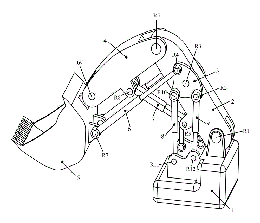
[0014] In the three-dimensional schematic diagram of a redundant front shovel excavation mechanism that can optimize the lifting force shown in Figure 1, the lower end of the boom 2 is connected to one end of the frame 1 through the hinge R1, and the upper end of the boom 2 is connected through the The hinge R5 is connected to one end of the arm 4, and the other end of the arm 4 is connected to the bucket 5 through the hinge R6; a pair of powerful triangles 3 are respectively connected to both sides of the boom 2 through the hinge R3, and a pair of buckets are hydraulically The cylinder liner ends of the cylinder 6 are respectively connected to the above-mentioned bucket 5 through the hinge R7, and the piston rod ends of the pair of bucket hydraulic cylinders 6 are respectively connected to the above-mentioned powerful triangle 3 through the hinge R4; The ends of the cylinder sleeves are respectively connected to the arm 4 through the hinge R8, the piston rod ends of the pair o...

Embodiment 2

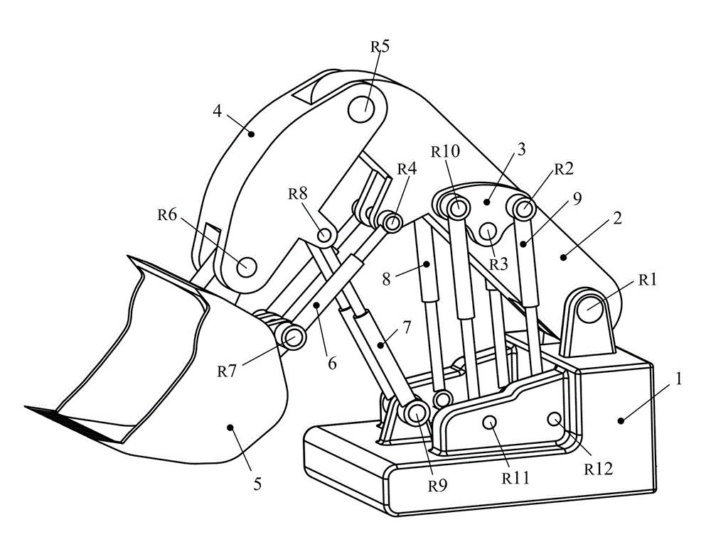
[0016] exist figure 2 In the three-dimensional schematic diagram of a redundant front shovel excavating mechanism capable of optimizing lifting force, the lower end of the boom 2 is connected to one end of the frame 1 through the hinge R1, and the upper end of the boom 2 is connected to the frame 1 through the hinge R5. One end of the stick 4 is connected, and the other end of the stick 4 is connected with the bucket 5 through the hinge R6; a pair of powerful cams 3 are respectively connected with both sides of the boom 2 through the hinge R3, and a pair of bucket hydraulic cylinders 6 The ends of the cylinder sleeves are respectively connected to the above-mentioned bucket 5 through the hinge R7, and the ends of the piston rods of the pair of bucket hydraulic cylinders 6 are respectively connected to the above-mentioned boom 2 through the hinge R4; the cylinder sleeve ends of the pair of stick hydraulic cylinders 7 The ends of the piston rods of the pair of arm hydraulic cyl...


PUM


Abstract

The invention discloses a motion redundancy face shovel excavating mechanism capable of optimizing lifting force, wherein a movable arm is hinged with a frame; a hopper rod is hinged with the movable arm; a bucket is hinged with the hopper rod; the frame, the movable arm, the hopper rod and the bucket form an open type tandem connection chain; a powerful triangle is hinged with the movable arm, the end part of the cylinder sleeve of the bucket hydraulic cylinder is hinged with the bucket, and the end part of the piston rod of the bucket hydraulic cylinder is hinged with the powerful triangle; the end part of the cylinder sleeve of the hopper rod hydraulic cylinder is hinged with the hopper rod, and the end part of the piston rod of the hopper rod hydraulic cylinder is hinged with the movable arm; the end part of the cylinder sleeve of a driving arm hydraulic cylinder is hinged with the powerful triangle, and the end part of the piston rod of a main driving arm hydraulic cylinder is hinged with the frame; and the end part of the cylinder sleeve of an auxiliary driving arm hydraulic cylinder is hinged with the powerful triangle, and the end part of the piston rod of the auxiliary driving arm hydraulic cylinder is hinged with the frame. The motion redundancy face shovel excavating mechanism provided by the invention has the characteristics of motion redundancy, large driving force arm, excellent flexibility and optimized input force.

Description

technical field [0001] The invention relates to an excavator, in particular to a working mechanism for a front shovel hydraulic excavator. Background technique [0002] Large-scale front shovel hydraulic excavator is the main tool for mining in open-pit coal mines, and its excavating working device is the main component to complete various functions of the excavator. There are few domestic studies on the working device of hydraulic front shovel excavator. Chinese patent CN200520035287.8 involves a A horizontal pushing mechanism of a front shovel operation device of a hydraulic excavator, characterized by the hinged bucket hydraulic cylinder piston rod and the front end of the boom, the hinged rear part of the stick with the front end of the boom, the hinged bucket with the front end of the stick, and the hinged bucket with the bucket. The ends of the cylinder barrel of the hydraulic cylinder are hinged, and the hinge points form a four-bar mechanism with a quadrilateral stru...

Claims


Application Information

Patent Timeline
Patent Type & Authority Applications(China)
IPC IPC(8): E02F3/342E02F3/38E02F3/42
Inventor 丁华锋曹文熬杨凤霞王园园曹宇付鸿晔
Owner YANSHAN UNIV
Why Eureka
Try Eureka