Light-source apparatus and projector

A light source and projection device technology, which can be applied to projection devices, lighting devices, components of lighting devices, etc., and can solve problems such as complex mechanical structures

Active Publication Date: 2012-10-10
CASIO COMPUTER CO LTD
View PDF14 Cites 20 Cited by
  • Summary
  • Abstract
  • Description
  • Claims
  • Application Information

AI Technical Summary

Problems solved by technology

On the other hand, in such projectors, it is often required to further increase the output of the semiconductor light-emitting element used for the light source, and to further increase the brightness of the projected image, but in the technology described in the above-mentioned patent documents, it is necessary to make the device Larger and more complex mechanical structures, etc., have limitations in meeting the above requirements

Method used


Image

  • Light-source apparatus and projector
  • Light-source apparatus and projector
  • Light-source apparatus and projector

Examples


Embodiment Construction

[0029] Embodiments of the present invention will be described with reference to the drawings.

[0030] An embodiment in which the present invention is applied to a DLP (registered trademark) system data projector device will be described below with reference to the drawings.

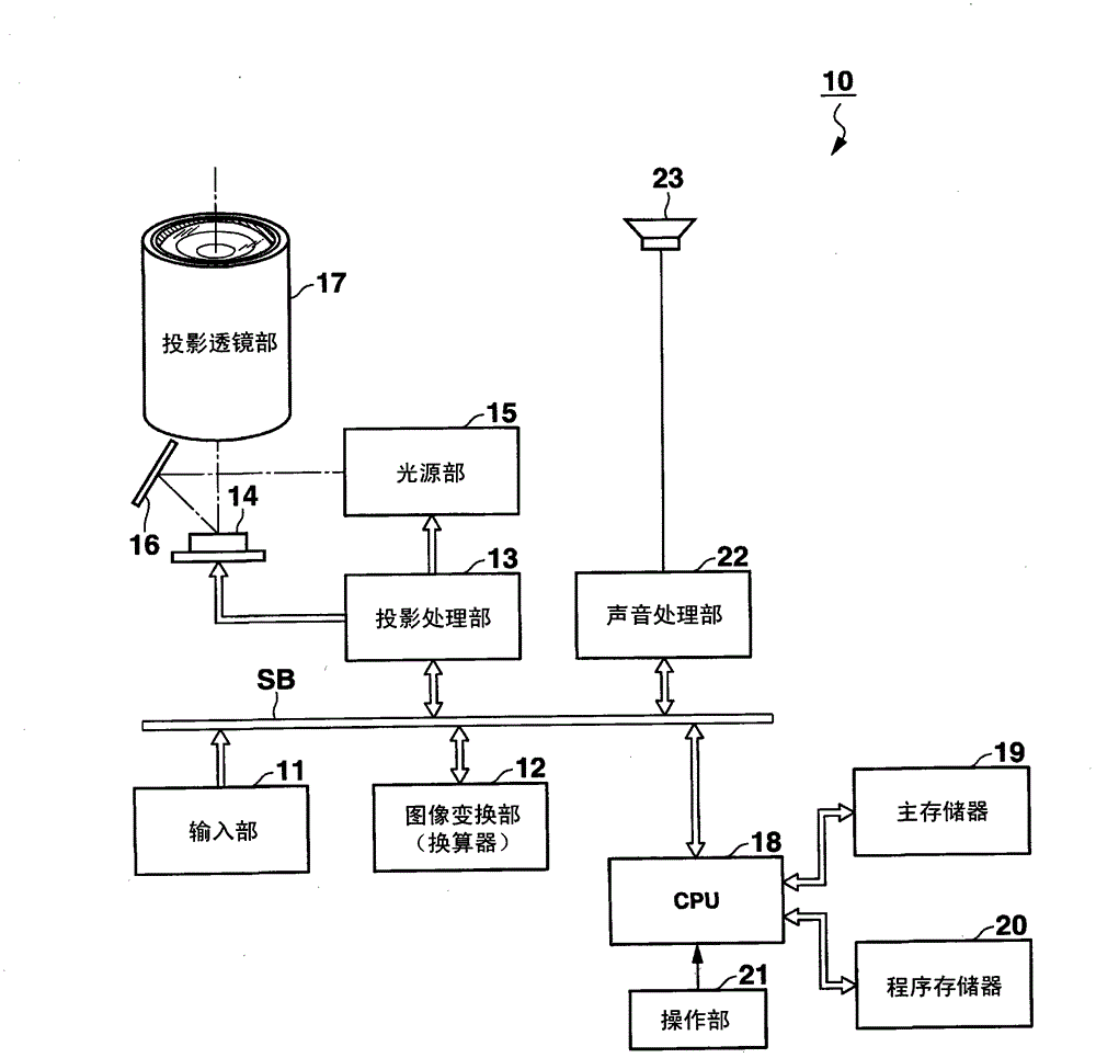
[0031] figure 1 It is a diagram showing a schematic functional configuration of the data projector device 10 according to the present embodiment.

[0032] The input unit 11 includes, for example, a pin jack (RCA) type video input terminal, a D-sub15 type RGB input terminal, and the like. The analog image signals of various standards input to the input unit 11 are digitized by the input unit 11 and sent to the image conversion unit 12 via the system bus SB.

[0033] The image conversion unit 12 is also called a scaler, and unifies the input image data into image data in a predetermined format suitable for projection, and sends the image data to the projection processing unit 13 .

[0034] At this time,...


PUM


Abstract

A projection apparatus includes a fluorescence plate including a fluorescence layer configured to emit fluorescence light beams upon irradiation of the excitation lights, a first lens array, provided on a light source side of the fluorescence plate and including a plurality of lenses arranged in an array to correspond with the light-emitting elements, and configured to collect the fluorescence light beams and emit the fluorescence light beams to be parallel with one another, and a projection unit configured to form an optical image using the fluorescence light beams obtained via the first lens array and project the optical image on a projection object.

Description

[0001] Cross References to Related Applications [0002] According to 35USC119, this application is based on the application dated March 28, 2011, and the application number is JP Japanese Patent Application No. 2011-070897, and claims its priority, including the description, claims, drawings and abstract. The entire content of the author is incorporated herein by reference. technical field [0003] The present invention relates to a projection device suitable for a DLP (Digital Light Processing) (registered trademark) type projector device using a semiconductor light emitting element. Background technique [0004] Conventionally, a technique such as JP-A-2010-164846 has been proposed, in which a phosphor wheel on which a plurality of sector-shaped phosphors are arranged and its rotational drive unit are swung by a motor and a crank mechanism, and the positions of the phosphors irradiated with light beams are cycled. Even if the output of the excitation source of the light ...

Claims


Application Information

Patent Timeline
Patent Type & Authority Applications(China)
IPC IPC(8): G03B21/20F21V13/00F21V9/10F21V9/40
CPCF21V9/10G03B21/204G03B21/208F21V13/00G03B21/2013H04N9/3164H04N9/3161
Inventor 荻野浩
Owner CASIO COMPUTER CO LTD
Why Eureka
Try Eureka