Organic electroluminescent element

An electroluminescence element and luminescence technology, applied in the direction of electroluminescence light sources, electrical components, organic semiconductor devices, etc., can solve the problems of short life, short life of blue phosphorescence, insufficient luminous efficiency, etc., and achieve high efficiency Effect

Inactive Publication Date: 2012-04-25
IDEMITSU KOSAN CO LTD
View PDF30 Cites 15 Cited by
  • Summary
  • Abstract
  • Description
  • Claims
  • Application Information

AI Technical Summary

Problems solved by technology

However, although the red phosphorescent element has reached the field of practical use, the life of the green and blue phosphorescent elements is shorter than that of the fluorescent element. In particular, the blue phosphorescence not only has a short life, but also has insufficient color purity and luminous efficiency. Not yet practical

Method used


Image

  • Organic electroluminescent element
  • Organic electroluminescent element
  • Organic electroluminescent element

Examples


no. 1 Embodiment approach

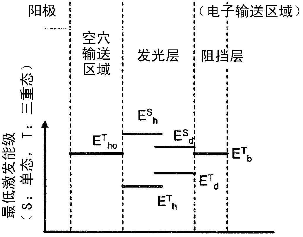
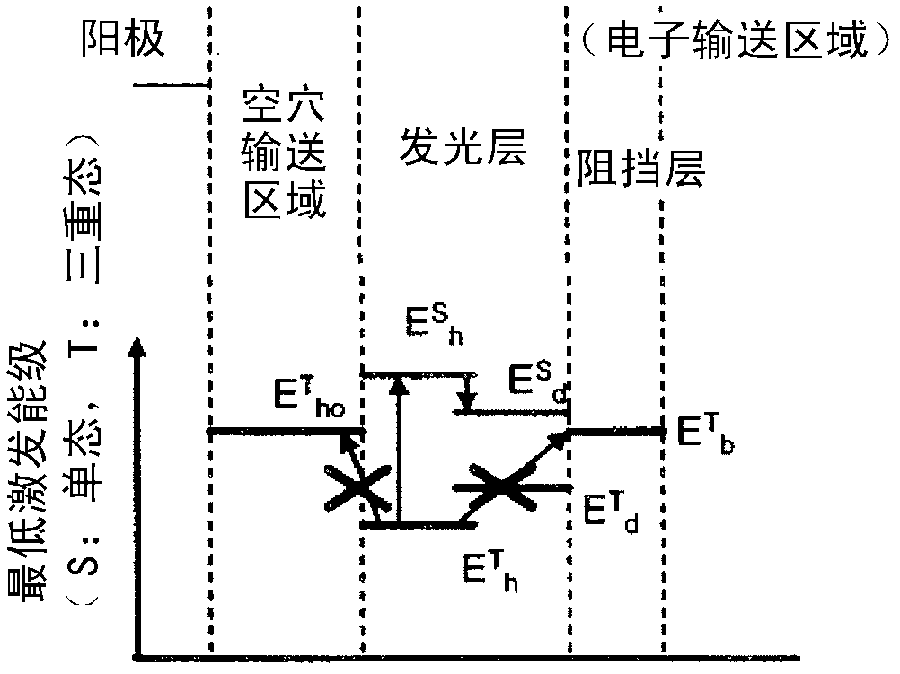
[0065] The present invention utilizes the TTF phenomenon. First, the TTF phenomenon will be described below. The holes and electrons injected from the anode and the cathode are recombined in the light-emitting layer to generate excitons. As known conventionally, the ratio of the rotational state is 25% for singlet excitons and 75% for triplet excitons. In previously known fluorescent devices, 25% of singlet excitons emit light when they relax to the ground state, but the remaining 75% of triplet excitons do not emit light but return to the ground state through thermal inactivation. Therefore, the theoretical limit value of the internal quantum efficiency of conventional fluorescent elements can be said to be 25%.

[0066] On the other hand, the behavior of triplet excitons generated inside organic substances has been theoretically studied. According to S.M.Bachilo et al. (J.Phys.Cem.A, 104, 7711 (2000)), if higher-order excitons such as the quintet state are assumed to imme...

no. 2 Embodiment approach

[0229] The device of the present invention may have a tandem device structure having at least two organic layer units including a light-emitting layer. An intermediate layer (also referred to as an intermediate conductive layer, an electrochemical generation layer, or CGL) exists between the two light-emitting layers. Each cell can be provided with an electron transport region. A unit in which at least one light-emitting layer is a fluorescent light-emitting layer and includes this light-emitting layer satisfies the above-mentioned requirements. Examples of specific stacking sequences are shown below. In addition, the light-emitting layer described below may be a laminate of a plurality of light-emitting layers, or may be an organic layer unit including a charge blocking layer of the third embodiment described later.

[0230] Anode / fluorescent layer / intermediate layer / fluorescent layer / blocking layer / cathode

[0231] Anode / fluorescent layer / blocking layer / intermediate layer...

no. 3 Embodiment approach

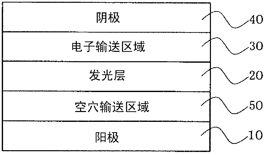
[0239] In this embodiment, an anode, a plurality of light-emitting layers, an electron transport region, and a cathode are sequentially provided, and a charge blocking layer is provided between any two light-emitting layers among the plurality of light-emitting layers, and the light-emitting layer close to the charge blocking layer is fluorescent. A light-emitting layer that satisfies the above-mentioned requirements.

[0240] As the structure of a suitable organic EL element according to the present embodiment, as described in Japanese Patent No. 4134280, U.S. Laid-Open Patent Publication US2007 / 0273270A1, and International Laid-Open Publication WO2008 / 023623A1, a stack of anodes, In the structure of the first light-emitting layer, the charge blocking layer, the second light-emitting layer, and the cathode, there is an electron transport region between the second light-emitting layer and the cathode, and the electron transport region has a structure for preventing the diffusio...


PUM


Abstract

Disclosed is an organic electroluminescent element provided with, at least, an anode, a light-emitting layer, an electron-transport band, and a cathode, in that order. The light-emitting layer includes a host and a dopant that exhibits fluorescence having a main peak wavelength no greater than 550 nm. The affinity Ad of the dopant is at least as great as the affinity Ah of the host, and the triplet energy E T d of the dopantis higher than the triplet energy E T h of the host. The electron-transport band is provided with a barrier layer adjacent to the light-emitting layer. The triplet energy E T b of the barrier layer is higher than E T h.

Description

technical field [0001] The present invention relates to an organic electroluminescence (EL) element, in particular to a high-efficiency organic EL element. Background technique [0002] If the organic EL element is classified according to its light emitting principle, it can be divided into two types: fluorescent type and phosphorescent type. When a voltage is applied to the organic EL element, holes are injected from the anode, and electrons are injected from the cathode, and these recombine in the light-emitting layer to form excitons. Singlet excitons and triplet excitons are generated at a ratio of 25%:75% by the statistical rule of electron spin. Since it is fluorescent and utilizes light emission based on singlet excitons, the limit of internal quantum efficiency is considered to be 25%. Fluorescent devices that use fluorescent materials have recently developed a longer lifespan technology, and although they are gradually being used in full-color displays such as mob...

Claims


Application Information

Patent Timeline
Patent Type & Authority Applications(China)
IPC IPC(8): H01L51/50H05B33/12
CPCH05B33/10H01L51/5036H01L51/5004C09B57/008H01L51/0059H01L51/006H01L51/0054H01L51/0055H01L51/5052H01L51/5012C09B3/78C09B57/00H05B33/14C09B1/00H01L51/5092H01L51/5096H01L51/0058H01L51/0056H01L51/5048H01L2251/552H10K85/624H10K85/623H10K85/622H10K85/626H10K85/633H10K85/631H10K50/11H10K2101/40H10K50/125H10K50/14H10K50/165H10K50/171H10K50/18H10K2101/30
Inventor 熊均河村祐一郎甚出行俊荻原俊成细川地潮
Owner IDEMITSU KOSAN CO LTD
Why Eureka
Try Eureka