
Touch screen

A touch screen and touch panel technology, which is applied in the input/output process of instruments, electrical digital data processing, and data processing, etc., can solve the problems of speed limit, touch accuracy limit, interference, etc. Small touch height, the effect of reducing the number of touches

Inactive Publication Date: 2012-10-10
BEIJING UNITOP NEW TECH CO LTD
View PDF3 Cites 8 Cited by
  • Summary
  • Abstract
  • Description
  • Claims
  • Application Information

AI Technical Summary

Problems solved by technology

[0013] One disadvantage of the projected capacitive touch screen is that the screen is not completely transparent due to the existence of the covering layer; another disadvantage is that the cost is high; another disadvantage is that it is susceptible to interference from the external environment (temperature, humidity, electric field); Speed ​​is limited; another disadvantage is that touch accuracy is limited by capacitance
[0014] Since the touch screen in the prior art is not ideal for small mobile devices and large screen devices, it is necessary to provide a touch screen that overcomes the shortcomings of the above-mentioned resistive and capacitive touch screens
[0015] The infrared touch screen in the prior art has a high touch height, which is easy to cause misidentification, and has poor anti-light performance

Method used

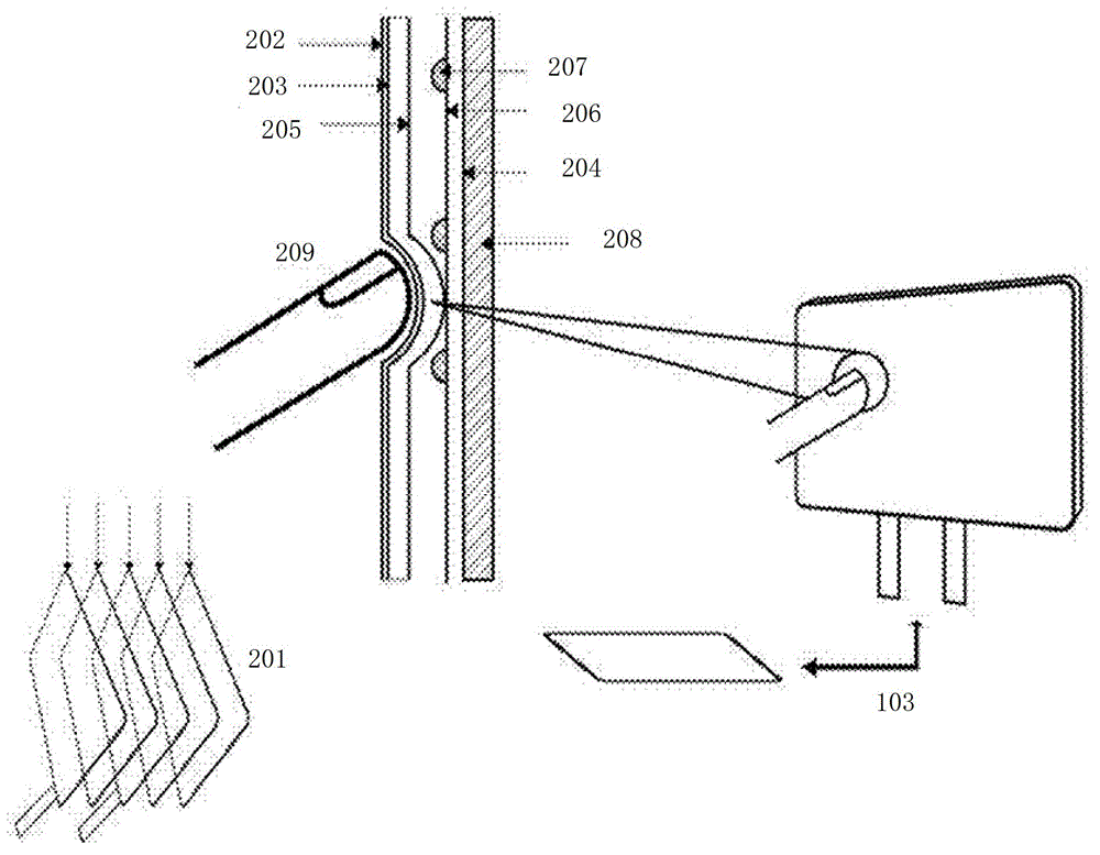
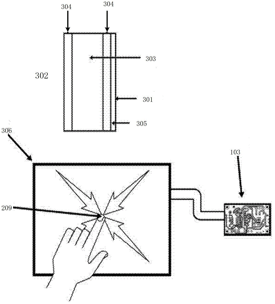

Image

  • Touch screen
  • Touch screen
  • Touch screen

Examples


Embodiment Construction

[0036] The technical solutions of the present invention will be clearly and completely described below in conjunction with specific implementation methods and accompanying drawings.

[0037] like Figure 5 As shown, it is a top view of the touch screen in an embodiment of the present invention and a schematic cross-sectional view along AA' in the top view. The touch screen in this embodiment includes a touch panel 501 (which can be a glass panel or a touch detection area) , a printed circuit board 502, an infrared emitting element 503, an infrared receiving element 504, and a light guide component. The printed circuit board 502 can be an integrated frame structure, or a frame structure formed by splicing four elongated structures end to end. Or for other shapes and structures, the frame-shaped printed circuit board 502 can be installed around the touch panel 501; the infrared emitting element 503 is installed on the adjacent two sides of the frame-shaped printed circuit board ...


PUM


Abstract

The invention discloses a touch screen. The touch screen comprises a touch panel, a printed circuit board, an infrared emitting element, an infrared receiving element and a light guide component, wherein the infrared emitting element and the infrared receiving element are arranged on the printed circuit board; and the light guide component is used for changing the propagation direction of a light beam emitted by the infrared emitting element so as to propagate the light beam along the touch surface of the touch panel, and changing the propagation direction of the light beam propagated along the touch surface of the touch panel so as to emit the light beam to the infrared receiving element. With the adoption of the touch screen, the coverage scope of the light beam is wide, the touch precision is high, the touch height is effectively reduced, and the high light resistance is provided.

Description

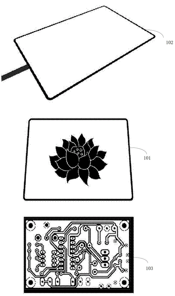
technical field [0001] The invention relates to a touch screen based on an infrared light network. Background technique [0002] With the development of multimedia technology, touch control technology has become a hot technology in today's human-computer interaction. The way of human-computer interaction (such as keyboard, mouse, etc.) of many products is gradually replaced by touch screen. These touch screens cover small screen devices such as mobile phones and car entertainment systems, to medium screen devices such as notebook computers, and then to large screen devices such as electronic whiteboards for teaching. [0003] Most of the existing touch screen systems are based on resistive and capacitive layers. Due to the low versatility of this system, it is inconvenient to expand in terms of application. [0004] like figure 1 Shown is a schematic diagram of a touch system in the prior art. The system includes an LCD display surface 101; a resistive or capacitive over...

Claims


Application Information

Patent Timeline
Patent Type & Authority Applications(China)
IPC IPC(8): G06F3/042
Inventor 尚晓东刘新斌
Owner BEIJING UNITOP NEW TECH CO LTD
Learn More