
Control method and communication device of optical module

A communication device and control communication technology, applied in the field of data communication, can solve the problems of management personnel injury, eye injury, optical module not being used, etc.

Active Publication Date: 2012-10-10
MAIPU COMM TECH CO LTD
View PDF3 Cites 12 Cited by
  • Summary
  • Abstract
  • Description
  • Claims
  • Application Information

AI Technical Summary

Problems solved by technology

[0003] For communication equipment with optical modules, especially those that support multiple optical modules, when they are used by users, the following problems often occur: only insert the optical module at the connector position of the optical module, but because the current The requirement does not involve the optical module, so the optical module is not used, and even the optical fiber is not connected
[0004] In response to this problem, the current communication equipment generally does not specialize in processing, and still powers on the optical module as in normal use. In this way, on the one hand, it will waste power resources, on the other hand, because the light emitted by the optical module is laser , may cause harm to management personnel, such as direct exposure to people's eyes will cause serious injury

Method used


Image

  • Control method and communication device of optical module
  • Control method and communication device of optical module
  • Control method and communication device of optical module

Examples


Embodiment Construction

[0028] In order to make the object, technical solution and advantages of the present invention clearer, the present invention will be described in detail below in conjunction with the accompanying drawings and specific embodiments.

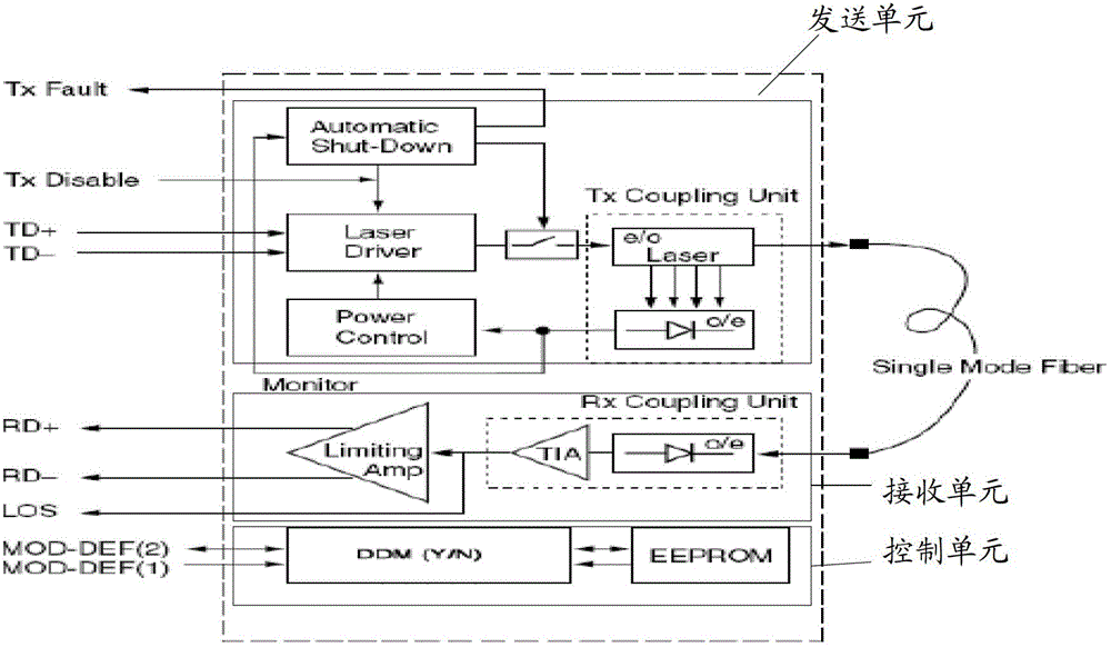
[0029] According to the definition of the SFP-MSA Association, a typical optical module on a communication device includes three parts: a sending unit, a receiving unit, and a control unit, as follows: figure 1 shown.

[0030] Among them, such as figure 1 As shown, the core of the sending unit is the semiconductor laser, which accounts for about 60% of the power consumption of the entire optical module, and is very easily affected by the internal temperature. Therefore, the control circuit of this part is also the most complicated, and the service life of the semiconductor laser is the shortest. The service life is equal to the service life of the optical module. Therefore, in the management / control signal group of the optical module, two signals...


PUM


Abstract

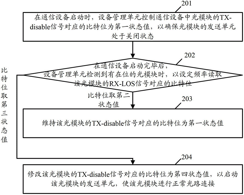
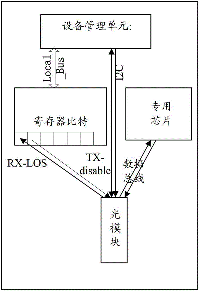
The invention provides a control method and communication device of an optical module. The control method comprises the steps that a register is arranged on the periphery of a device management unit, a TX-disable signal and an RX-LOS signal of the optical module respectively correspond to any two bytes of the register; when the communication device is started, the byte corresponding to the TX-disable signal of the optical module is controlled as a first status value to ensure that a transmission unit of the optical module stays at a closed status; and after the communication device is started, if an on-site optical module is detected, the byte corresponding to the RX-LOS signal of the optical module is read with a set frequency, so that whether the byte corresponding to the TX-disable signal of the optical module is maintained as the first status value, i.e. the transmission unit of the optical module is kept at the closed status or the byte corresponding to the TX-disable signal of the optical module is changed to a fourth status value to start the transmission unit of the optical module, and the connection of a normal light path can be performed by the optical module.

Description

technical field [0001] The present application relates to data communication technology, in particular to a control method of an optical module and a communication device. Background technique [0002] At present, communication devices supporting optical fiber connections are becoming more and more common. Among them, in order to facilitate the maintenance and replacement of components on communication equipment, SFP-MSA (Small Form-factor Pluggable Transceiver Multisource Agreement, which is an association composed of Agilent, Finisar and other companies) will support optical fiber connection. Devices used for optical / electrical and electrical / optical signal conversion are uniformly defined as easily pluggable optical modules. [0003] For communication equipment with optical modules, especially those that support multiple optical modules, when they are used by users, the following problems often occur: only insert the optical module at the connector position of the optica...

Claims


Application Information

Patent Timeline
IPC IPC(8): H04B10/08
Inventor 程鸿博
Owner MAIPU COMM TECH CO LTD
Learn More