Wearable equipment and state detection method and device

A wearable device, state detection technology, applied in the field of mobile communication, can solve problems such as insufficient reliability and accuracy

Inactive Publication Date: 2020-02-18
VIVO MOBILE COMM CO LTD
View PDF10 Cites 6 Cited by
  • Summary
  • Abstract
  • Description
  • Claims
  • Application Information

AI Technical Summary

Problems solved by technology

[0006] The embodiment of the present invention provides a wearable device, a state detection method and a device to solve the problem of insufficient reliability and accuracy of the wearing detection method in the prior art

Method used


Image

  • Wearable equipment and state detection method and device
  • Wearable equipment and state detection method and device
  • Wearable equipment and state detection method and device

Examples


Embodiment 1

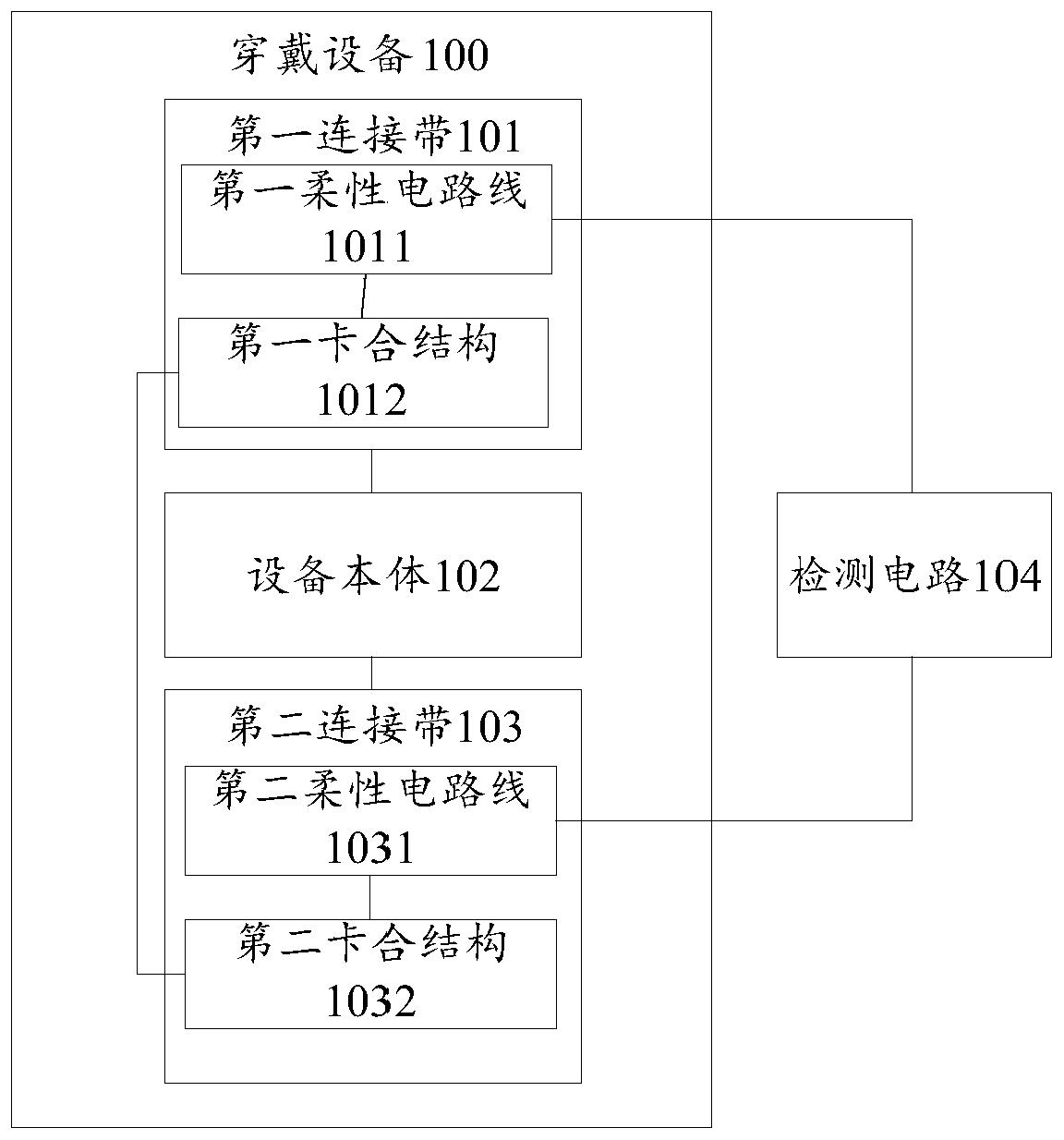
[0029] refer to figure 1 , shows a schematic structural diagram of a wearable device provided by an embodiment of the present invention.

[0030] Such as figure 1 As shown, the wearable device 100 may include: a first connecting strap 101 , a second connecting strap 103 and a device main body 102 .

[0031] Such as figure 1 As shown, the first end of the first connecting band 101 can be connected to the device main body 102, the first end of the second connecting band 103 can be connected to the device main body 102, and the second end of the first connecting band 101 is provided with a conductive first An engaging structure 1012 , the second end of the second connection strip 103 is provided with a conductive second engaging structure 1032 matched with the first engaging structure 1012 .

[0032] The first engaging structure 1012 can be engaged with the second engaging structure 1032 , and when the first engaging structure 1012 and the second engaging structure 1032 are en...

Embodiment 2

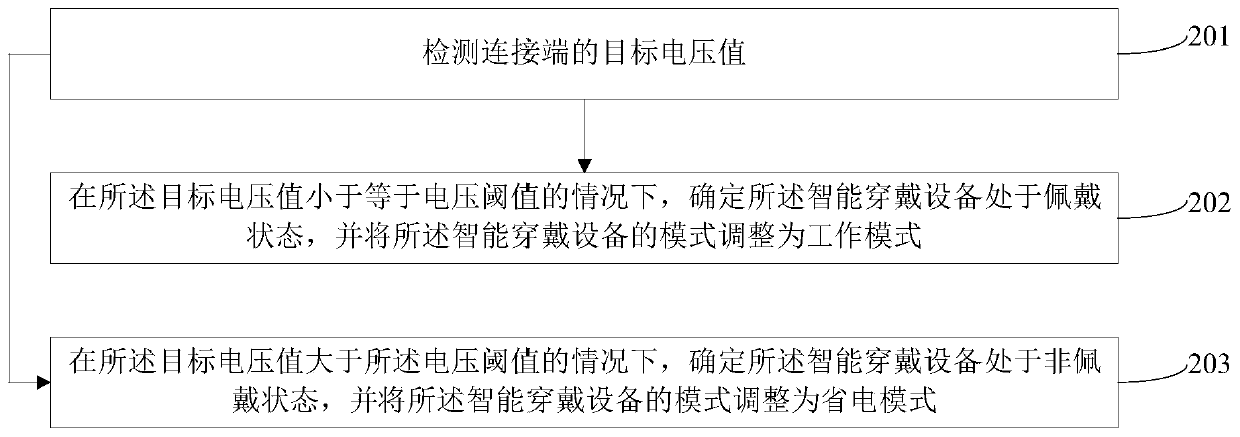
[0038] refer to figure 2 , which shows a flow chart of the steps of a state detection method provided by an embodiment of the present invention. The state detection method for the wearable device in the first embodiment above may specifically include the following steps:

[0039] Step 202: Detect the target voltage value of the connection terminal.

[0040] In the embodiment of the present invention, wearable device is a general term for wearable devices that are intelligently designed and developed for daily wear using wearable technology. Wearable devices can be smart electronic devices such as smart watches, smart bracelets, smart glasses and smart clothing. equipment.

[0041] The connecting end refers to the end on the wearable device for the user to wear, for example, refer to Figure 2a , showing a schematic diagram of a smart watch endowed with electrical characteristics provided by an embodiment of the present invention, as shown in Figure 2aAs shown, the smart w...

Embodiment 3

[0066] refer to image 3 , which shows a flow chart of the steps of a state detection method provided by an embodiment of the present invention. The state detection method can be applied to a wearable device at an electrical characteristic connection end, and may specifically include the following steps:

[0067] Step 301: Detect the target voltage value of the connection terminal.

[0068] In this embodiment of the present invention, the specific implementation of the above-mentioned step 301 is similar to the specific implementation of the above-mentioned step 201 in the first embodiment, and the implementation process of the step 301 can refer to the description in the above-mentioned second embodiment, the embodiment of the present invention is here No more details.

[0069] After the target voltage value of the connection terminal is detected, step 302 is performed, or step 303 is performed.

[0070] Step 302: When the target voltage value is less than or equal to a vol...


PUM


Abstract

The invention provides wearable equipment and a state detection method and device. A first end of a first connecting band is connected with an equipment main body, a first end of a second connecting band is connected with the equipment main body, a second end of the first connecting band is provided with a conductive first clamping structure, and a second end of the second connecting band is provided with a conductive second clamping structure matched with the first clamping structure; a first flexible circuit line is arranged in the first connecting band, a second flexible circuit line is arranged in the second connecting band, and the first end of the first flexible circuit line and the first end of the second flexible circuit line are both connected with the detection circuit; the second end of the first flexible circuit line is connected with the first clamping structure, and the second end of the second flexible circuit line is connected with the second clamping structure. According to the invention, the detection accuracy and reliability of the wearing state can be improved, the mode of the wearable device can be adjusted in real time according to the wearing state, and the purpose of power saving can be achieved while the work of the wearable device is not influenced.

Description

technical field [0001] The invention relates to the technical field of mobile communication, in particular to a wearable device, a state detection method and a device. Background technique [0002] With the popularization of smart wearable devices, the functions of smart wearable devices are becoming more and more abundant, and the problem brought about is that the battery life of wearable devices is reduced. [0003] At present, most smart wearable devices have a mechanism to detect whether they are worn or not. When it is recognized that the wearable device is not in the wearable state, it is considered that the device is not in use and can enter a more power-saving low-power consumption mode, such as automatic disconnection Bluetooth network, or stop the push of various information notifications, etc. On the smart wearable device for children, parents are often notified in time whether the wearable device has been removed by others by identifying the wearing status. [...

Claims


Application Information

Patent Timeline
Patent Type & Authority Applications(China)
IPC IPC(8): G06F3/01G06F1/3234
CPCG06F3/014G06F1/3234
Inventor 陈作行
Owner VIVO MOBILE COMM CO LTD
Why Eureka
Try Eureka