Construction method of beam longitudinal bar anchorage for stiffened steel structural column-beam column joints

A beam-column joint and steel structure technology, which is applied in building construction, construction and other directions, can solve the problems of increased engineering volume, difficult welding operations, and difficult construction, and achieves accelerated construction speed, convenient and fast opening, and improved anchorage. quality effect

Inactive Publication Date: 2015-11-11
广西建工第五建筑工程集团有限公司
View PDF4 Cites 8 Cited by
  • Summary
  • Abstract
  • Description
  • Claims
  • Application Information

AI Technical Summary

Problems solved by technology

[0002] Due to its strong bearing capacity, high shear and flexural strength, the stiffened steel structural column is a kind of reinforced vertical load-bearing structural column widely used in high-rise and super high-rise buildings. It is a steel-concrete composite structure that has been promoted and used in recent years. One of the top ten new technologies in the construction industry in 2010, the longitudinal reinforcement at the beam-column joints is often very dense, and the construction is extremely difficult; the current method of anchoring the beam longitudinal reinforcement at the beam-column joints is mainly welded to the stiffening ring plate of the circular steel frame , this method will result in insufficient welding space, difficult welding operation and the inability to guarantee the weld size, and difficult to control the welding quality. The steel bars cannot be anchored reliably, and the force requirements of the design cannot be guaranteed; in addition, a large number of welding operations will lead to slow construction progress and double the amount of work, resulting in a significant increase in construction costs

Method used


Image

  • Construction method of beam longitudinal bar anchorage for stiffened steel structural column-beam column joints
  • Construction method of beam longitudinal bar anchorage for stiffened steel structural column-beam column joints
  • Construction method of beam longitudinal bar anchorage for stiffened steel structural column-beam column joints

Examples


Embodiment Construction

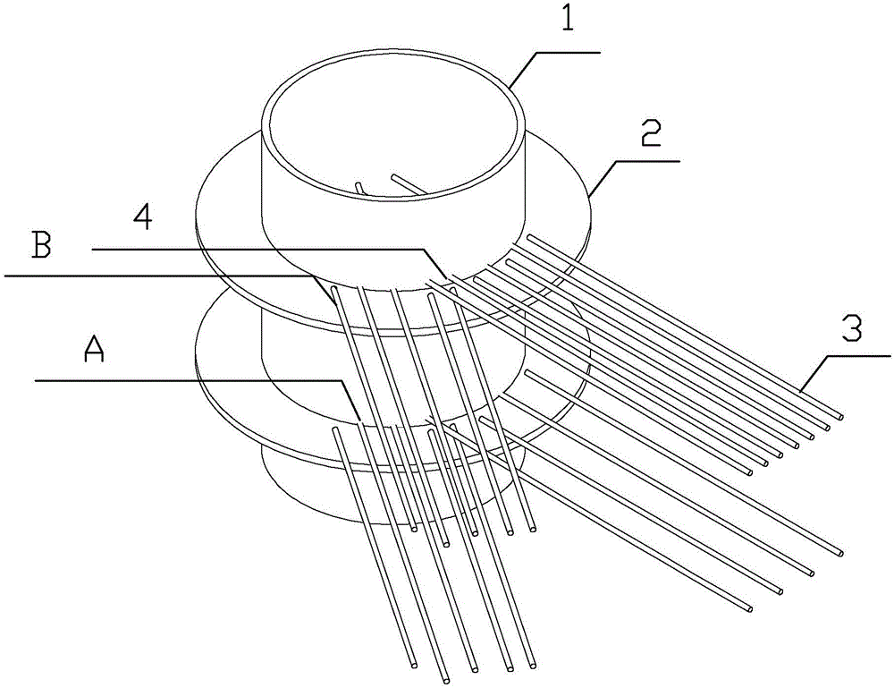
[0070] A stiff steel structure column-beam-column joint beam longitudinal bar anchoring construction method, the stiff steel structure column includes a steel bone column, and the stiff steel structure column-beam-column joint beam longitudinal bar anchorage construction method refers to a steel An anchoring construction method between bone columns and reinforced concrete beam-column joints, the method is to use welding and opening holes to interpenetrate the anchorage construction between the rigid steel structure columns and the steel bars of the longitudinal bars of the reinforced concrete beam-column joints , this method first carries out three-dimensional modeling, and uses AutoCAD and other software combining two-dimensional and three-dimensional through the detailed design to loft and model the design drawings according to 1:1 (see figure 1 -Schematic diagram of the three-dimensional modeling of the "rigid steel structure column-beam-column joint beam longitudinal reinfo...


PUM


Abstract

A construction method of beam longitudinal bar anchorage for stiffened steel structural column-beam column joints is characterized in that longitudinal bars of stiffened steel structural column and reinforced concrete beam joints are anchored by means of welding and hole cutting and penetrating. The method includes: performing three-dimensional modeling, performing setting-out and modeling on design drawings according to a ratio of 1:1 through detailed design by means of two-dimensional and three-dimensional software such as AutoCAD, optimally arranging the bars according to rules of the detailed design, determining an anchoring mode of the bars and hole positions, and performing editing with AutoCAD or explorer TSSD to make drawings so as to guide field actual construction. The basic rules of the detailed design include simultaneous use of welding and hole cutting, to be specific, hole cutting is optimally performed at the premise of meeting the requirement on section loss rate; beam corner bars are not holed as far as possible; beam-end crossing bars are stacked layer by layer. The method has the advantages that the bars are provided with sufficient welding space, welding quality is evidently improved, welding quantity is reduced, construction speed is increased, and engineering quality is guaranteed.

Description

technical field [0001] The invention relates to a construction method, in particular to a rigid steel structure column-beam-column joint beam longitudinal bar anchor construction method. Background technique [0002] Due to its strong bearing capacity, high shear and flexural strength, the stiffened steel structural column is a kind of reinforced vertical load-bearing structural column widely used in high-rise and super high-rise buildings. It is a steel-concrete composite structure that has been promoted and used in recent years. One of the top ten new technologies in the construction industry in 2010, the longitudinal reinforcement at the beam-column joints is often very dense, and the construction is extremely difficult; the current method of anchoring the beam longitudinal reinforcement at the beam-column joints is mainly welded to the stiffening ring plate of the circular steel frame , this method will result in insufficient welding space, difficult welding operation an...

Claims


Application Information

Patent Timeline
Patent Type & Authority Applications(China)
IPC IPC(8): E04B1/58E04B1/41
Inventor 李书文吴炳豪黄后玉唐玉婷韦永梦
Owner 广西建工第五建筑工程集团有限公司
Why Eureka
Try Eureka