
Tail-wheel-free combined left-turning driven disk plow

A driving disc, combined technology, applied in ploughs, agricultural machinery, agricultural machinery and implements, etc., can solve the problems of failing to meet agronomic requirements and reducing downward soil force, so as to reduce processing costs and raw material consumption. , the effect of strong soil entry ability and strong lateral force balance ability

Inactive Publication Date: 2012-10-17
FUJIAN AGRI & FORESTRY UNIV
View PDF4 Cites 4 Cited by
  • Summary
  • Abstract
  • Description
  • Claims
  • Application Information

AI Technical Summary

Problems solved by technology

However, the existing drive disc plow has a relatively shallow plowing depth for dry farming, mainly because the soil friction resistance and the disc rolling resistance have an upward component force when the tillage disc rotates and cuts the soil, which leads to a decrease in the downward force into the soil and dry The plowing depth is relatively shallow, which fails to meet the agronomic requirements of most dryland farming. On the contrary, the conventional plow has good soil penetration performance. Therefore, the combination of the two types of plows can increase the soil penetration moment and improve the dryness. Cultivation depth

Method used


Image

  • Tail-wheel-free combined left-turning driven disk plow
  • Tail-wheel-free combined left-turning driven disk plow
  • Tail-wheel-free combined left-turning driven disk plow

Examples


Embodiment Construction

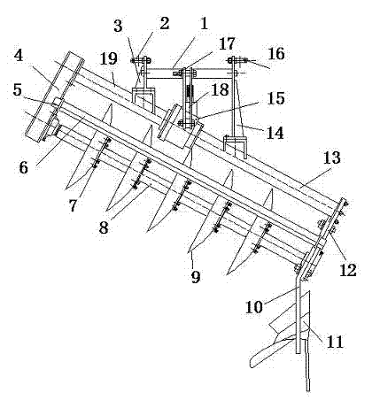
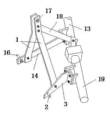
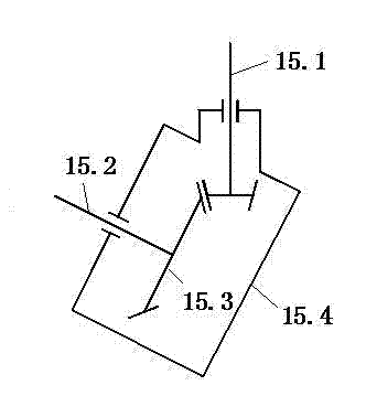
[0022] Such as Figure 1 to Figure 6 As shown, a six-plow body tailless wheel combined left-turning drive disc plow is provided. figure 1 It is the overall structure diagram, the structure of the suspension frame assembly, the central transmission assembly, the side transmission box and the hook type plow column is as follows: Figure 2~Figure 6 As shown, this example is composed of 5 drive-type tillage discs and 1 conventional plow, that is, the tail plow, forming a combined plow with a width of six plow bodies. The side is transmitted to the disc cutter shaft, which drives the tillage disc to rotate for tillage. The tail plow is drawn for plowing because it is fixedly connected to the right side plate, and the soil is turned to the left during tillage.

[0023] The suspension frame assembly is connected with the main beams 13, 19 and the central transmission assembly 15. The central transmission assembly 15 includes a central transmission box 15.4 and a transmission assembl...


PUM


Abstract

A tail-wheel-free combined left-turning driven disk plow is a drive tillage implement, consisting of a drive tillage disk and a moldboard plow, and having the advantages of low oil consumption, low traction resistance, high production efficiency and high oil penetrating performance. The structure of the disk plow comprises a suspension bracket assembly, a central transmission assembly, a main beam, a side transmission box assembly, a disk tillage component assembly, a right side plate, a tail plow assembly, and on the like. With the adoption of the implement, the complex tail wheel device is eliminated and the machining cost and the raw material consumption are reduced; the lateral force is mainly balanced by a plow side plate of the moldboard plow arranged on the tail part, so the balancing property is high, the disk plow is suitable for paddy field dry tillage and dry land tillage, and capable of being developed and used in large dry farming areas, so that the novel tillage implement which saves energy, reduces emission, enhances gain and reduces cost is provided to the agricultural industry.

Description

technical field [0001] The invention relates to a driving disc plow, in particular to a tailless wheel combined left-turning driving disc plow which combines a driving disc plow and a mould-type plow, and belongs to the field of agricultural machinery. Background technique [0002] The drive disc plow is known for its low fuel consumption, low traction resistance and high productivity. Compared with the conventional plow, the productivity is increased by 39%~70.5%, and the fuel is saved by 18%~32.5%. With good passing performance and strong obstacle-crossing ability, popularizing the drive disc plow is of great significance to energy saving and emission reduction in agricultural production. However, the existing drive disc plow has a relatively shallow plowing depth for dry farming, mainly because the soil friction resistance and the disc rolling resistance have an upward component force when the tillage disc rotates and cuts the soil, which leads to a decrease in the downwa...

Claims


Application Information

Patent Timeline
Patent Type & Authority Applications(China)
IPC IPC(8): A01B9/00A01B17/00A01B71/06
Inventor 朱亨银何金成吴喜平方文熙
Owner FUJIAN AGRI & FORESTRY UNIV
Learn More