Hammer forging device for forming complicated long-axis forgings applied to radial forging machine

A radial forging, long-axis technology, applied in forging/pressing/hammer devices, engine components, forging/pressing/hammering machinery, etc., can solve the problems that local features cannot be formed, difficult to realize, and difficult to part molds

Inactive Publication Date: 2012-10-17
SHANGHAI JIAO TONG UNIV
View PDF7 Cites 8 Cited by
  • Summary
  • Abstract
  • Description
  • Claims
  • Application Information

AI Technical Summary

Problems solved by technology

However, some types of long-axis parts blanks cannot or are difficult to be formed by traditional rolling, roll forging and extrusion methods: such as parts with multiple branch features in cross-section, such parts can be It is difficult to part the mold. If extrusion is used, it is difficult to carry out due to the gradual change of the workpiece size along the axis direction; and for parts with helical features, especially if the cross-sectional profile size changes along the axis direction, it is also difficult to use traditional methods. In addition, for large forgings with complex shapes, if die forging is used for forming, the tonnage requirements for die forging equipment will be very high, which often exceeds the capacity of existing equipment, so it is difficult to achieve
[0003] Dong Xianghuai and others invented a progressive rolling method (patent number: CN200910055960) that uses simple tools to produce complex-shaped long-axis parts or blanks. This method can form profiles and blanks that can change the shape of the section along the axial direction. , but it needs to go through multiple times of reciprocating rolling, and cannot form fine local features

Method used


Image

  • Hammer forging device for forming complicated long-axis forgings applied to radial forging machine
  • Hammer forging device for forming complicated long-axis forgings applied to radial forging machine
  • Hammer forging device for forming complicated long-axis forgings applied to radial forging machine

Examples


Embodiment

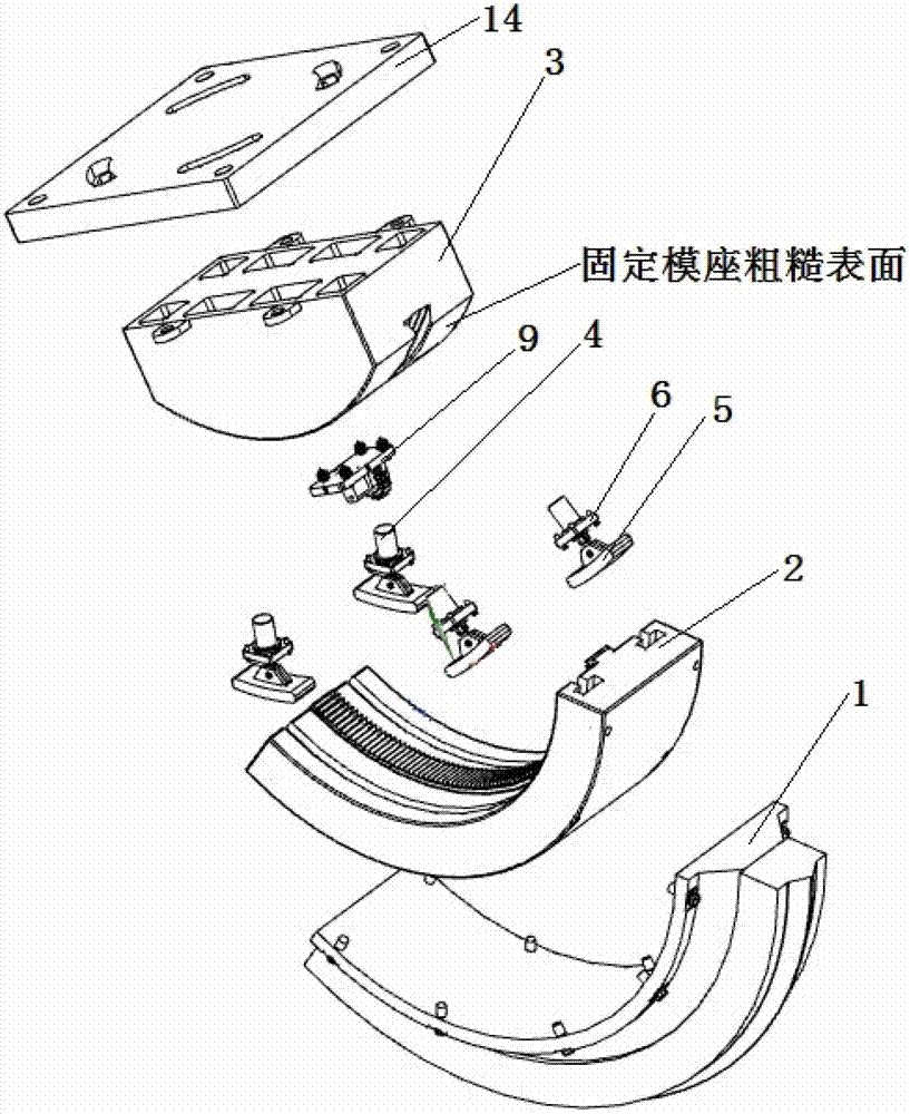
[0032] A hammer forging device used for forming complex long-shaft forgings on a radial forging machine, its structure is as follows figure 1 As shown, it is mainly composed of the following components: a forging unit installed on the hammer head of each radial forging machine. The other parts of each forging unit are the same except for the forming module. Its structure includes: forming module 1, dynamic Mold base 2, fixed mold base 3, template 14, compression block control assembly 4, compression block 5, compression block control assembly fixing plate 6, gear mounting seat 9, etc. Radial forging machines generally use 4 hammerheads, and this example also uses 4 hammerheads, which are respectively installed in the forming modules 1 of the 4 forging units to form plastic deformation zones.

[0033] The structures of several main components of the present invention are described in detail below.

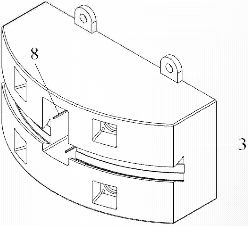
[0034] The fixed die base 3 includes the following structure: there are 4 moun...


PUM


Abstract

The invention relates to a hammer forging device for forming complicated long-axis forgings applied to a radial forging machine. The hammer forging device consists of forging units which are respectively mounted on hammers of a precise forging machine and have the same structure, wherein each forging unit consists of a fixed mold seat, a moving mold seat, a forming module and the like. Different from the existing forging method, according to the hammer forging device, the relative positions of the moving mold seats and the fixed mold seats are maintained by using compressed slide blocks, when the compressed slide blocks are opened, driving gears mounted on the fixed mold seats drive tooth rings machined at the top ends of dovetails of the moving mold seats so as to realize the circumferential feeding of the moving mold seats, and thus, variable plastic deformation zones are formed by regions among the forming modules; and blanks are clamped to make axial and rotational movement by using a clamping head of the radial forging machine, so that the blanks are progressively formed in a piecewise manner, and then, the long-axis forgings which need multiple mold parting directions and have complicated cross sectional shapes, helical line characteristics and larger sizes can be forged.

Description

technical field [0001] The invention belongs to the technical field of plastic forming, and in particular relates to a hammer forging device for forming complex long-axis forgings on a radial forging machine. Background technique [0002] Long-axis parts are commonly used in mechanical devices. Using forging technology to produce long-axis parts blanks can significantly reduce the amount of subsequent cutting and improve product quality. However, some types of long-axis parts blanks cannot or are difficult to be formed by traditional rolling, roll forging and extrusion methods: such as parts with multiple branch features in cross-section, such parts can be It is difficult to part the mold. If extrusion is used, it is difficult to carry out due to the gradual change of the workpiece size along the axis direction; and for parts with helical features, especially if the cross-sectional profile size changes along the axis direction, it is also difficult to use traditional methods...

Claims


Application Information

Patent Timeline
Patent Type & Authority Applications(China)
IPC IPC(8): B21J7/16B21J13/00B21K1/06
Inventor 董湘怀栾谦聪吴云剑马智慧
Owner SHANGHAI JIAO TONG UNIV
Why Eureka
Try Eureka