Rotary table capable of being used for machining knock-over plate
A technology of rotating worktable and stripping plate, applied in metal processing equipment, metal processing machinery parts, manufacturing tools, etc., can solve the problems of prolonging production cycle, consuming manpower and material resources, and scrapping parts, so as to improve production efficiency and reduce The effect of human and material resources
- Summary
- Abstract
- Description
- Claims
- Application Information
AI Technical Summary
Problems solved by technology
Method used
Image

Examples
Embodiment Construction
[0022] The present invention is described in further detail now in conjunction with accompanying drawing. These drawings are all simplified schematic diagrams, which only illustrate the basic structure of the present invention in a schematic manner, so they only show the configurations related to the present invention.
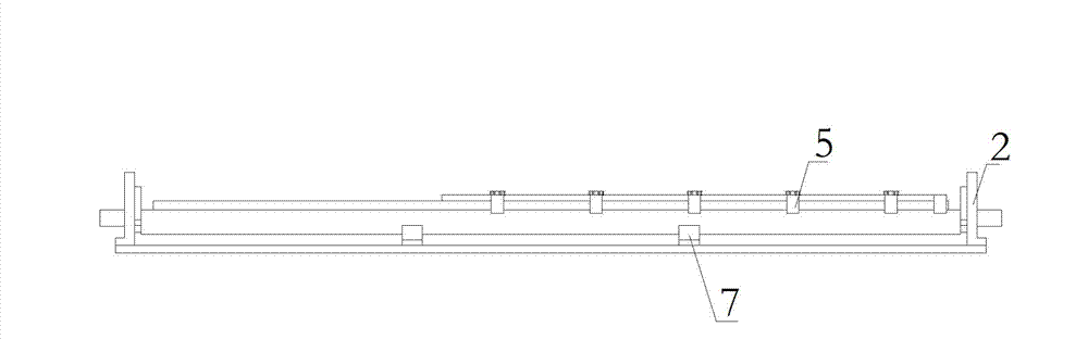
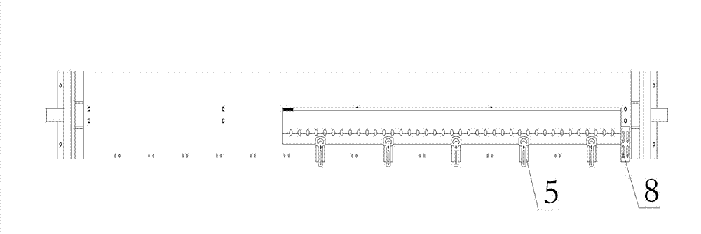
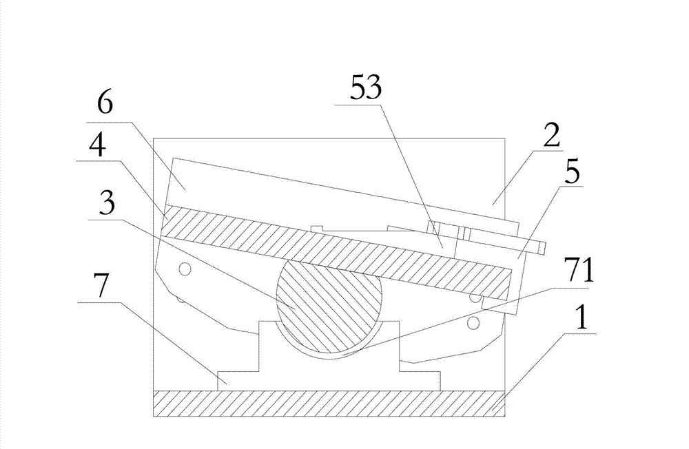
[0023] Such as Figure 1 to Figure 7 The schematic diagram of the structure of a rotary table that can be used to process stripping plates is shown. It has a base 1 installed on the guide rail of the machine tool. The two ends of the base 1 are fixedly connected with fixing seats 2, and the two fixing seats 2 are connected by bearings. There is a rotating shaft 3 that can rotate freely. The surface of the outer ring of the rotating shaft 3 is formed with a horizontal tangent plane in the axial direction, and the horizontal tangent plane is rectangular in shape. The plate seat plate 4 is provided with five clamping devices 5 for fixing the stripping plate on t...
PUM
 Abstract
Description
Claims
Application Information
PatSnap Eureka turns technology decisions into work you can execute. Powered by our Innovation Knowledge Graph, it runs expert workflows across engineering, life sciences, materials and intellectual property. Get your review-ready output in minutes.


