Coal bunker capable of preventing chute blockage and coal agglomeration

A technology to prevent coal blockage and coal bunker, applied in containers, packaging, transportation and packaging, etc., can solve problems such as hidden dangers of personal safety, unstable coal supply, and inability to meet the load requirements of dispatching, so as to eliminate the occurrence of vicious accidents, Improve efficiency and safety, eliminate the effect of coal blocking and shed coal

Inactive Publication Date: 2012-10-17
陕西华电瑶池发电有限公司
View PDF0 Cites 3 Cited by
  • Summary
  • Abstract
  • Description
  • Claims
  • Application Information

AI Technical Summary

Problems solved by technology

[0002] Caking, blockage, and shed coal occur frequently in the existing coal bunkers, and boiler adjustment is difficult to achieve normally, and cannot meet the load requirements of dispatching; the amount of combustion-supporting oil is large, the load rate is low, and the economical operation level is low; the raw coal bunker forms a flue gas channel , the high-temperature flue gas in the furnace reverses, which may easily cause the coal feeder and the belt to burn out; the coal supply is unstable, resulting in coking in the furnace and poor slag discharge; the high bed pressure may easily cause the boiler to be forced to stop; personnel entering the warehouse Frequent excavation and cleaning of coal deposits in the interior, there is a big hidden danger to personal safety

Method used


Image

  • Coal bunker capable of preventing chute blockage and coal agglomeration

Examples


Embodiment Construction

[0011] The present invention will be described in detail below in conjunction with the accompanying drawings and specific embodiments.

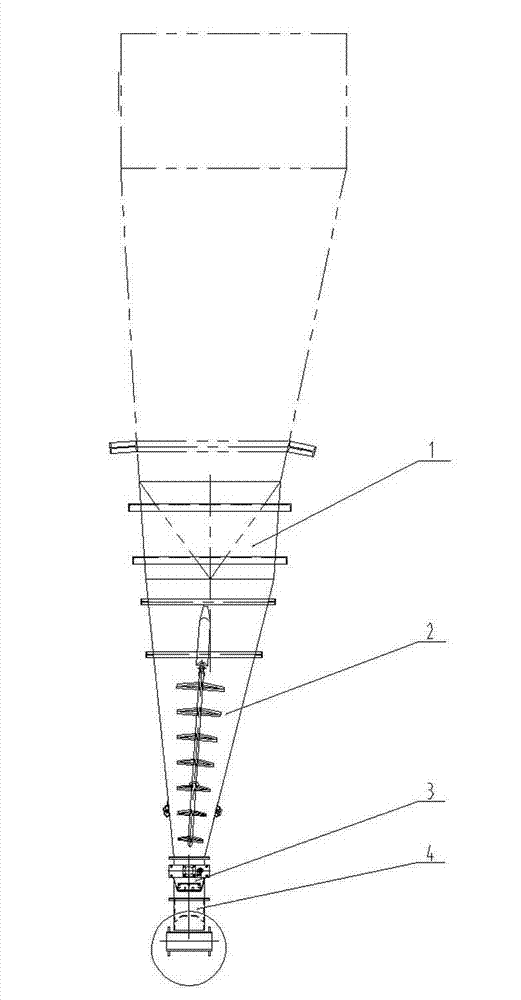
[0012] see figure 1 , the present invention includes a coal bunker 1, a loosening machine 2, and a hydraulic cut-off door 3. The coal bunker 1 is conical, and a looser 2 is arranged in the lower vertebral part of the coal bunker 1, and a hydraulic cut-off door is set at the coal outlet of the coal bunker 1. The door 3, the lower part of the hydraulic cut-off door 3 is connected with the coal feeder through the inlet nipple 4; the hydraulic cut-off door 3 is connected with a controller.

[0013] The angle between the bunker wall and the horizontal plane of the above-mentioned coal bunker 1 is greater than or equal to 73 degrees, and all of them are arc-curved surfaces, which well solves the problem of coal accumulation at the corners of the rectangular coal bunker.

[0014] The inner wall of the above coal bunker 1 is provided with a liner, t...


PUM


Abstract

The invention relates to a coal bunker capable of preventing chute blockage and coal agglomeration. The technical problem to be solved by the invention is to provide a coal bunker capable of preventing chute blockage and coal agglomeration. The coal bunker capable of preventing chute blockage and coal agglomeration can alleviate the labor intensity of workers and risk during clearance as well as avoid fatal accident of burning a coal feeder. In order to solve the technical problem, the technical scheme provided by the invention is that the coal bunker capable of preventing chute blockage and coal agglomeration comprises a coal bunker, a loosen machine, and a hydraulic stop valve. The coal bunker is cone-shaped. The loosen machine is arranged in a cone part at the lower part of the coal bunker. The hydraulic stop valve is arranged at a coal outlet of the coal bunker. The lower part of the hydraulic stop valve is connected with the coal feeder through an inlet short piece. The hydraulic stop valve is connected with a controller. According to the coal bunker capable of preventing chute blockage and coal agglomeration provided by the invention, the coal feeding quality is greatly improved, and phenomena of smoke fleeing, rise of outlet temperature and manual clearance can be avoided; chute blockage and coal agglomeration are eliminated; the fatal accident of burning the coal feeder is thoroughly eliminated, the cost is saved, and the benefit and safety are improved.

Description

technical field [0001] The invention relates to a coal bunker for preventing coal blocking and shed coal. Background technique [0002] Caking, blockage, and shed coal occur frequently in the existing coal bunkers, and boiler adjustment is difficult to achieve normally, and cannot meet the load requirements of dispatching; the amount of combustion-supporting oil is large, the load rate is low, and the economical operation level is low; the raw coal bunker forms a flue gas channel , the high-temperature flue gas in the furnace reverses, which may easily cause the coal feeder and the belt to burn out; the coal supply is unstable, resulting in coking in the furnace and poor slag discharge; the high bed pressure may easily cause the boiler to be forced to stop; personnel entering the warehouse Frequent excavation and cleaning of coal deposits in the mines pose a great potential safety hazard. Contents of the invention [0003] The technical problem solved by the present inven...

Claims


Application Information

Patent Timeline
IPC IPC(8): B65D88/64
Inventor 计彬鹏曹忠宁朱松柏
Owner 陕西华电瑶池发电有限公司
Why Eureka
Try Eureka