
Container handling machine and machine for container handling

A container processing machine and container technology, applied in liquid processing, conveyors, bottling machines, etc., can solve the problems of container jamming, container damage, and difficult to avoid clean room air pollution, etc., to achieve improved cleanliness and pollution elimination Effect

Inactive Publication Date: 2012-10-17
KRONES AG
View PDF7 Cites 34 Cited by
  • Summary
  • Abstract
  • Description
  • Claims
  • Application Information

AI Technical Summary

Problems solved by technology

[0016] Conventional grippers often cause problems in clean room atmosphere operation due to their curved path controllers: e.g. at the transfer arms of the transfer star wheel, which can be difficult to avoid as the curved path controllers are worn and require lubrication Contamination of the clean room atmosphere, or curved path controllers are technically complex due to the difficulty of installing a clean room seal
In practice, however, problems can arise if containers handed over by the grippers of the transfer starwheel are not immediately and properly accelerated by the air flow and carried away
As a result, container jamming can occur which can result in damage to the container and require operator intervention

Method used


Image

  • Container handling machine and machine for container handling
  • Container handling machine and machine for container handling
  • Container handling machine and machine for container handling

Examples


Embodiment Construction

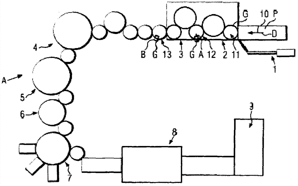
[0083] figure 1 The container treatment plant A shown in as a non-limiting example comprises, as part of the heating module 1, a transfer section 10 for the preforms P, in which the preforms at, for example, the holding mandrels D or the inner grippers are held. The preforms P are transferred, for example, to a further transfer section 11 defined by a transfer star wheel in an intermediate module 2 in which (optionally) a selective heat treatment of the preforms P is carried out (cf. Figure 29 , 30 ). In this process, the preform is brought into contact with temperature-controlled contact elements acting as clamping jaws in order to impose a temperature profile that varies, for example, in the circumferential direction. This is followed by the blow molding module 3 as another container handling machine, in which the transfer star wheel 12 is moved by the transfer arm A and the gripper G in the state of pitch distortion compensation. The temperature-controlled preform is tr...


PUM

PropertyMeasurementUnit
lengthaaaaaaaaaa

Abstract

A container treatment machine with at least one gripper, which can be compulsorily transported along a predetermined transport section for handling a preform or container during transport and / or acceptance and / or delivery, and including, at a holder retaining at least two gripper claws, at least one controllable electric or magnetic drive for the gripper claws, where the gripper claws can be moved relative to each other in opening and closing directions and at least between defined gripping and release positions, and where each gripper claw can be individually separately actuated by the drive in the opening and / or closing direction relative to another gripper claw of the gripper. Alternately, both gripper claws can be actuated together in the same direction.

Description

technical field [0001] The invention relates to a container handling machine and a method of handling containers. As container handling machines, the present invention includes stretch blow molding machines, preform transport sections, filling machines, labeling machines, sterilizers, rinsers, transport buffers, and the like. Therein, the container handling machine has at least one gripper which can be forcibly conveyed along a predetermined conveyor for handling preforms or containers during the conveying and / or receiving and / or delivery process. Background technique [0002] US 5 253 911 A discloses a controlled gripper (gripper), in which an electric servomotor is mounted on the respective holder of the two gripping jaws, the electric servomotor resists opening with a spring The force of the turning cam pivots the clamping jaws symmetrically in the closing direction. The clamping jaws not only move symmetrically in opposite directions, but also forcibly assume exactly p...

Claims


Application Information

Patent Timeline
Patent Type & Authority Applications(China)
IPC IPC(8): B65G47/92B65G47/86B29C49/42
CPCB67C7/00B29C49/421B29C49/42B29C49/78B29C49/4252B65G29/00B29C49/4205B65G47/847B67C3/24B29C49/4236B29C49/42069B29C49/42073B29C49/42075B29C49/42095B29C49/42099B29C49/42362B29C49/42418B29C2049/7878
Inventor F·温兹格
Owner KRONES AG
Learn More