

Production method of steel plate for heavy-gauge pressure vessel
A pressure vessel and large thickness technology, which is applied in the production field of steel plates for large thickness pressure vessels, can solve problems such as difficulty in meeting the requirements of pressure vessels, and achieve the effects of enhancing market competitiveness, uniform organization and low cost
Inactive Publication Date: 2012-10-17
WUYANG IRON & STEEL +1
View PDF1 Cites 21 Cited by
- Summary
- Abstract
- Description
- Claims
- Application Information
AI Technical Summary
Problems solved by technology
According to the current GB713-2008, the maximum thickness of the normalizing type Q370R is 60mm. The current thickness specification is difficult to meet the requirements of the steel plate for pressure vessels for large thickness steel plates. The production method of large thickness Q370R steel plates needs to be solved urgently
Method used
View moreImage
Smart ImageViewing Examples

Examples
Embodiment 1
Embodiment 2
Login to View More PUM
| Property | Measurement | Unit |
|---|---|---|
| Thickness | aaaaa | aaaaa |
| Yield strength | aaaaa | aaaaa |
| Tensile strength | aaaaa | aaaaa |
Abstract
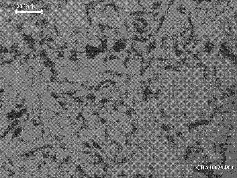
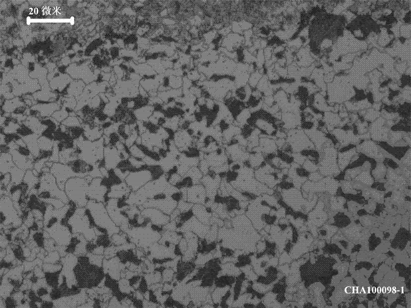
The invention discloses a steel plate for a heavy-gauge pressure vessel, and a preparation method thereof. Chemical components of the steel plate for the heavy-gauge pressure vessel are obtained through melting the following components, by weight, 0.15-0.18% of C, 0.25-0.50% of Si, 1.50-1.60% of Mn, 0.020% or less of P, 0.012% or less of S, 0.030-0.050% of Nb and 0.020-0.050% of Al; and the steel plate structure is a ferrite and pearlite structure. The design of the chemical components of the steel plate of the invention is characterized in that low price C and Mn are adopted for solution strengthening, small amounts of alloy elements are added, and water cooling is adopted after normalizing to accelerate cooling to make the steel plate have excellent mechanical performances, a uniform structure, good comprehensive performances and welding performances, and an enhanced market competitiveness. The steel plate has the following advantages: 1, the mechanical performances are good, and the yield strength and the tensile strength are largely higher than thinner specification performance indexes; 2, the low temperature impact energy is high, and the impact energy at -20DEG C is above 180J; and the largest thickness of the steel plate can reach 78mm.
Description
technical field [0001] technical field [0001] The invention relates to a production method of a steel plate for a pressure vessel with a large thickness. Background technique [0002] The basic requirements of steel for pressure vessels are mainly reflected in three aspects: (1) have good mechanical properties; (2) have good process properties; (3) have good corrosion resistance and oxidation resistance. The thickness of steel plates for pressure vessels is mostly 6-50 mm. According to the current GB713-2008, the maximum thickness of normalized Q370R is 60mm. The current thickness specifications are difficult to meet the requirements of large thickness steel plates for pressure vessel steel plates. The production method of large thickness Q370R steel plates needs to be solved urgently. Contents of the invention [0003] The object of the present invention is to provide a steel plate for a large thickness pressure vessel. [0004] The object of the present invention is...
Claims
Login to View More Application Information
Patent Timeline
 IPC IPC(8): C22C38/12
Inventor李红文赵文忠韦明胡丽周
OwnerWUYANG IRON & STEEL