Diffuser and centrifugal fan equipped with same

A technology of centrifugal fan and diffuser, which is applied to components of pumping devices for elastic fluids, machines/engines, non-variable pumps, etc., and can solve the problem of insufficient diffusion of diffusers and low working efficiency of centrifugal fans and other problems, to achieve the effect of sufficient pressure expansion, hindering backflow, and increasing air volume

Inactive Publication Date: 2012-10-17
NANJING LG PANDA APPLIANCES
View PDF3 Cites 3 Cited by
  • Summary
  • Abstract
  • Description
  • Claims
  • Application Information

AI Technical Summary

Problems solved by technology

[0005] The invention aims to solve the technical problems of insufficient diffusion of the existing diffuser and low working efficiency of the existing centrifugal fan

Method used


Image

  • Diffuser and centrifugal fan equipped with same
  • Diffuser and centrifugal fan equipped with same
  • Diffuser and centrifugal fan equipped with same

Examples


Embodiment 1

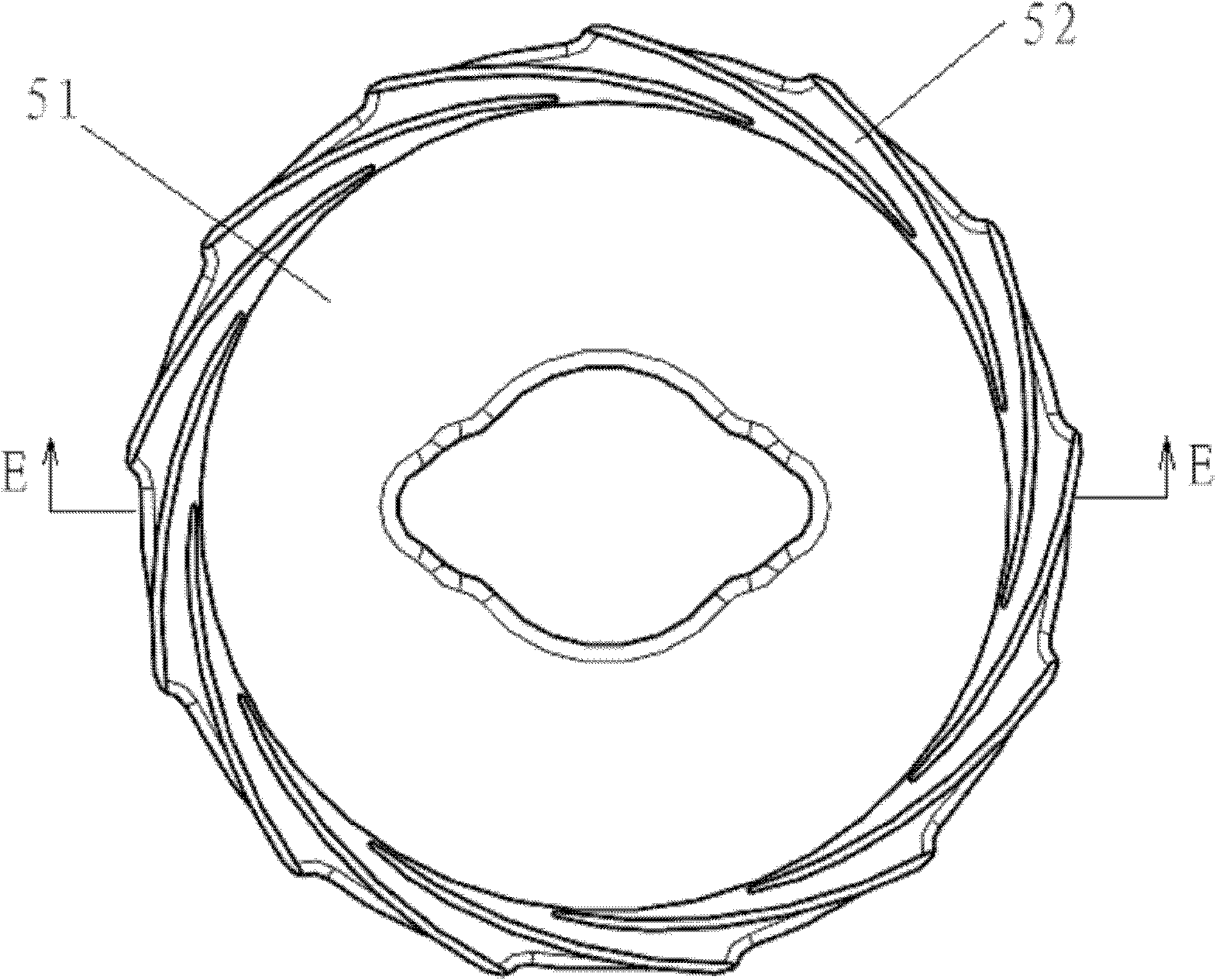
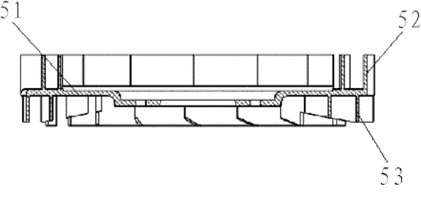
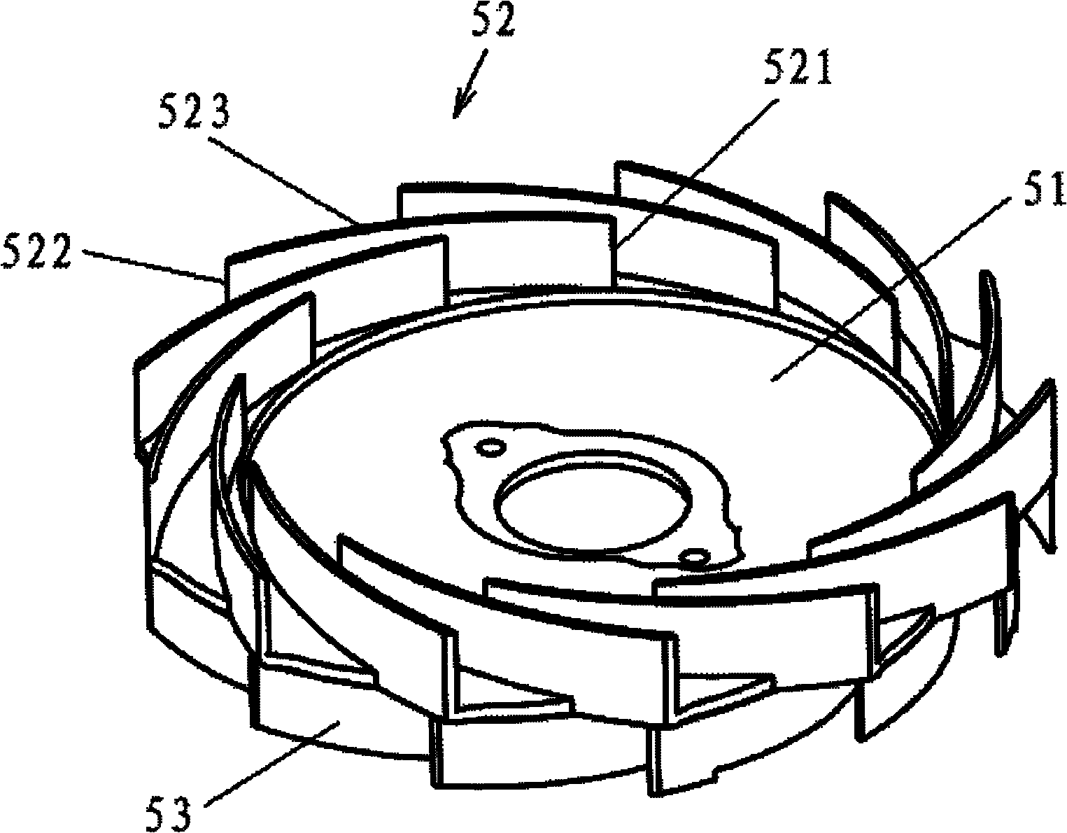
[0049] refer to Figure 3 to Figure 10 . in, image 3 It is a three-dimensional structural schematic diagram of the diffuser in the centrifugal fan of the present invention; Figure 4 is the top view structural diagram of the diffuser; Figure 5 express Figure 4 The F-F section view. Image 6 , Figure 7 Represent the structure of the first embodiment of the centrifugal fan of the present invention; Figure 8 , Figure 9 and Figure 10 The structure of the impeller in the first embodiment of the centrifugal fan of the present invention is shown.

[0050] The first embodiment of the centrifugal fan of the present invention includes a motor 2 installed in a motor casing 1, an impeller 3, a casing 4 and a diffuser. in

[0051] The impeller 3 includes an upper cover plate 31 , a lower cover plate 32 and several blades 33 . The upper cover plate 31 of the impeller 3 has a central through hole. Several blades 33 of the impeller 3 are spaced from each other and evenly ar...

Embodiment 2

[0056] refer to Figure 11 , Figure 12 . Figure 11 A schematic cross-sectional structure representation of the second embodiment of the centrifugal fan of the present invention; Figure 12 It shows the three-dimensional structure diagram of the casing in the second embodiment of the centrifugal fan of the present invention.

[0057] The case 4 has an upper cover portion 41 and a cylindrical portion 42 integral with the upper cover portion 41 . A plurality of rectangular openings 44 are uniformly arranged on the cylindrical portion 42 along the circumferential direction, and an air inlet 43 is provided in the center of the upper cover portion 41 of the casing 4 . On the upper cover plate 31 of the impeller 3, along the circumference of the air inlet 43, an air inlet baffle ring 45 integrally formed with the upper cover plate 31 is provided to ensure that the air entering by the air inlet 43 of the casing 4 can pass through the impeller 3 The central through hole of the up...

Embodiment 3

[0060] see Figure 13 . Figure 13 It shows the schematic cross-sectional structure diagram of the third embodiment of the centrifugal fan of the present invention.

[0061] The third embodiment of the centrifugal fan of the present invention is a combination of the first embodiment and the second embodiment of the centrifugal fan, that is, the first baffle ring 6 is set on the upper cover plate 31 of the impeller 3, and the casing 4 The second baffle ring 7 is arranged on the top, and the first baffle ring 6 and the second baffle ring 7 are arranged in a staggered manner to play a double function of preventing backflow. The other structures of the third embodiment of the centrifugal fan, such as the motor housing, motor, impeller and diffuser, are basically the same as those of the first embodiment, and will not be repeated here.


PUM


Abstract

The invention provides a diffuser and a centrifugal fan. The diffuser comprises a separator plate, a plurality of front guide blades uniformly arranged at the periphery of the front side of the separator plate and a plurality of back guide blades uniformly arranged at the periphery of the back side of the separator plate, the periphery of the front side of the separator plate is provided with an inclined portion, the inclined portion has an inclined surface, the thickness of the inclined portion of an air flow channel decreases gradually from a position close to the center of the separator plate to a position of the outer rim of the separator plate, and bottom ends of the front guide blades of the air flow channel are arranged on the inclined surface of the air flow channel. The diffuser of the invention provides sufficient diffusion, and at the same time can realize the optimum diffusion amount through designing the angle of inclination of the inclined surface relative to the separator plate. The centrifugal fan of the invention is equipped with the diffuser of the invention. The centrifugal fan of the invention can avoid the linear loss caused by insufficient diffusion, and therefore the centrifugal fan of the invention has high work efficiency.

Description

technical field [0001] The invention relates to a diffuser and a centrifugal fan equipped with the diffuser. Background technique [0002] According to the flow direction of the incoming and outgoing airflow, fans can be divided into two types: axial flow fans and centrifugal fans. Among them, the air in the centrifugal fan flows into the centrifugal fan from the axial direction and is exported from the circumferential direction, which has the characteristics of high wind pressure, so the centrifugal fan is widely used in ceiling-mounted air cleaners, vacuum cleaners, etc. [0003] Traditional centrifugal fan, including motor, impeller, diffuser and casing etc. The impeller includes an upper cover plate, a lower cover plate and several blades. like figure 1 , figure 2 As shown, the diffuser includes a partition 51, several pieces of leading guide vanes 52 uniformly arranged on the outer circumference of the front of the partition 51, and several pieces of rear guide van...

Claims


Application Information

Patent Timeline
Patent Type & Authority Applications(China)
IPC IPC(8): F04D29/44
Inventor 杨攀
Owner NANJING LG PANDA APPLIANCES
Why Eureka
Try Eureka