Anti-vibration mount

A technology of anti-vibration installation and installation holes, applied in the direction of non-rotational vibration suppression, etc., can solve the problem of the stability of the fixed connection, without considering the elastic body and other problems, and achieve the effect of improving durability and relaxing elastic force

Active Publication Date: 2015-12-16
KOKOKU INTECH CO LTD +1
View PDF7 Cites 0 Cited by
  • Summary
  • Abstract
  • Description
  • Claims
  • Application Information

AI Technical Summary

Problems solved by technology

[0006] In the prior art described above, in Patent Document 1, there is one metal plate, and the mounting to one vibrating body through the mounting hole of the metal plate can be securely fixed by screwing with a small screw or the like. To the other mounting body, it is carried out by fitting the protruding part of the elastic body fixed on the above-mentioned metal plate. There is a problem in the stability of the fixed connection, and it has to be admitted that the elastic body cannot be fixed in order to ensure strength. The wall thickness is made into a thin-walled structure
[0007] In addition, in Patent Document 2, since the metal plate is fitted and fixed to the elastic body, it becomes a half-split structure, which must be composed of four pieces divided into four, and the elastic body itself is also in order to maintain strength. Problem that cannot be constructed thinly
[0008] Moreover, for the clamping screw fixed to the vibrating body via the elastic body, the elastic body holding the clamping screw in the mounting hole is not considered at all.

Method used


Image

  • Anti-vibration mount
  • Anti-vibration mount
  • Anti-vibration mount

Examples


Embodiment Construction

[0028] Hereinafter, an embodiment of the present invention will be described with reference to the drawings.

[0029] [Example]

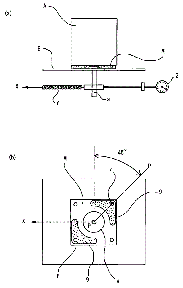
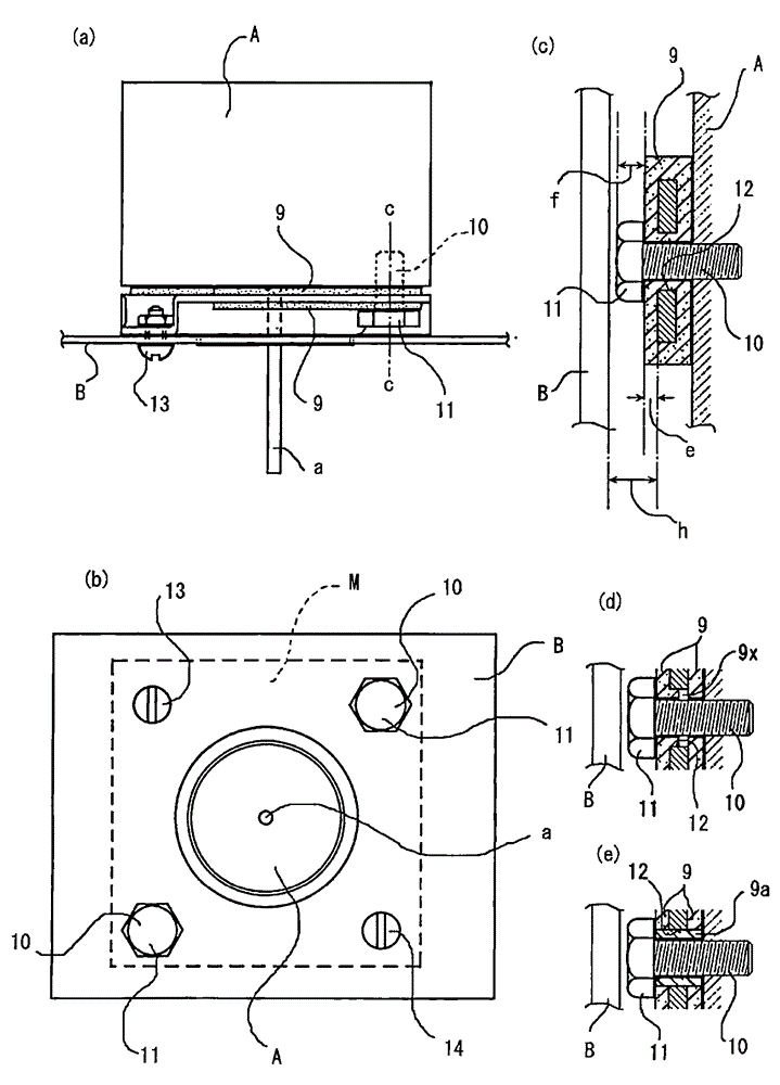
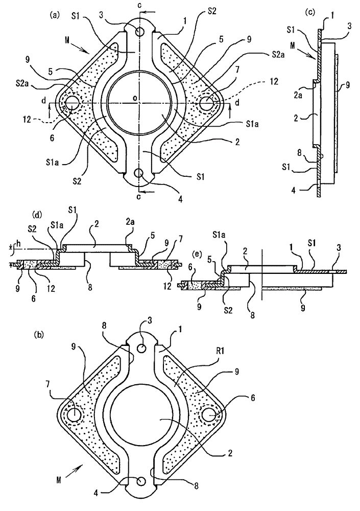
[0030] In the figure, 1 denotes a rigid plate made of a rigid material such as metal and rigid synthetic resin as the skeleton of the anti-vibration mounting member M, and has a central hole 2 in one direction. The upper and lower parts of the vertical direction are provided with high-level surfaces S1 of the mounting holes 3 and 4 as a contact surface with the mounting body B, and are provided with steps 5, 5 passing through the height h on the left and right with the center hole 2 as the center. The low surface S2 that expands in the left-right direction is provided with left and right mounting holes 6 and 7 sandwiching the center hole 2 to form a contact side with the vibrating member A on the back surface R1 side of the mounting holes 6 and 7. In addition, the above-mentioned hard board 1 can be formed in a square shape with a central hole 2 in the ...


PUM


Abstract

The invention provides an anti-vibration assembling set, being characterized in that the single material of a metal plate is enough,only part of an anti-vibration elastic body is covered on part of the plate so as to save the size of the metal plate as much as possible and to reduce the usage amount of the elastic body,and the elastic body for antivibration, and anti-vibration mounting piece which can form thin wall integrally are arranged in the inner surface of the mounting hole of a clamping screw. The anti-vibration assembling set is an nti-vibration assembling set formed by a hard plate and is characterized in that the hard plate is provided with a central hole, and is formed by a high-post surface which is provided with mounting holes up and down and is propped to a mounting body, and a low-post surface which is provided with mounting holes left and right formed by jump, thus forming an inner surface of the left and right mounting holes, the low-post surface including the inner surface, and the adhered elastic body on the opposite back surface of the inner surface,and the anti-vibration assembly is propped to the other vibration part through the elastic body, and can be fixed through a fastening part inserted in the mounting hole.

Description

Technical field [0001] The present invention is used to prevent mechanical vibration, and relates to a vibration-proof mounting member for vibration-proof supporting a vibrating body such as a stepping motor on a mounting body such as a frame. Background technique [0002] Various OA equipment, for example, a facsimile machine, a printer copier, etc., in which a vibrating body such as a stepping motor is fixedly connected to a support body such as a housing provided with an electronic circuit and an electronic device by a screw stopper or the like is known. [0003] Specifically, there is known an anti-vibration mount that uses an elastic material such as rubber as the anti-vibration material and sandwiches a metal plate in a frame structure to give a certain strength (for example, refer to Patent Documents 1 and 2). [0004] Patent Document 1: JP 2003-232403 No. [0005] Patent Document 2: JP 2003-232404 No. [0006] In the above-mentioned prior art, in Patent Document 1, the metal pl...

Claims


Application Information

Patent Timeline
Patent Type & Authority Patents(China)
IPC IPC(8): F16F15/08
Inventor 森久直树清水昭彦大竹利明
Owner KOKOKU INTECH CO LTD
Why Eureka
Try Eureka