Check patentability & draft patents in minutes with Patsnap Eureka AI!

Surface structure of missile

A surface structure, missile technology, applied in the direction of projectiles, offensive equipment, weapon types, etc., can solve the problems of large air resistance, affecting flight speed and distance, etc.

Inactive Publication Date: 2012-10-17
王仲彦
View PDF0 Cites 1 Cited by
  • Summary
  • Abstract
  • Description
  • Claims
  • Application Information

AI Technical Summary

Problems solved by technology

[0002] At present, the surface of the missile is designed to be smooth. When the missile is flying, the air forms a viscous effect on the surface of the missile. The air resistance is large, which affects the flight speed and distance.

Method used


Image

  • Surface structure of missile
  • Surface structure of missile

Examples


Embodiment Construction

[0007] The present invention will be further described below in conjunction with the description of the drawings and specific embodiments.

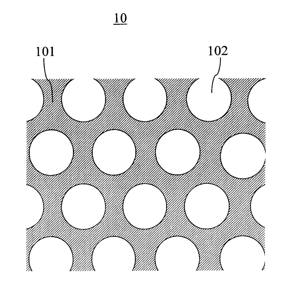
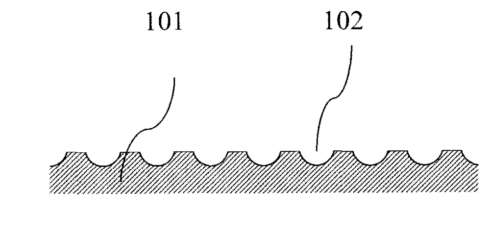
[0008] Please refer to the attached figure 1 and see attached figure 2 , the present invention provides a surface structure of the missile, which includes circular pits 102 uniformly distributed on the surface 101 of the missile 10, equal in size, and with a certain depth, and nearly bowl-shaped.

[0009] It is an alternative content of the present invention that the present invention is applied to artillery shells, bullets, rockets, aircraft, etc.

[0010] The above content is a further detailed description of the present invention in conjunction with specific preferred embodiments, and it cannot be assumed that the specific implementation of the present invention is limited to these descriptions. For those of ordinary skill in the technical field of the present invention, without departing from the concept of the present invention, s...


PUM


Abstract

The invention provides a surface structure of a missile, comprising nearly-bowl-shaped round pits, and the round pits are uniformly distributed on the surface of the missile, equal in size, and have a certain depth. Compared with a design that the surface of the existing missile is smooth, the surface structure disclosed by the invention can reduce the viscous effect of air on the surface of the missile, and reduce the air resistance of the missile in the process of flight, thereby speeding up the flight, and increasing the flight distance.

Description

technical field [0001] The invention relates to a missile surface structure. Background technique [0002] At present, the surface of the missile is designed to be smooth. When the missile is flying, the air forms a viscous effect on the surface of the missile, and the air resistance is large, which affects the flight speed and distance. Contents of the invention [0003] In order to overcome the above-mentioned deficiencies in the prior art, the present invention provides a surface structure of a missile, which includes uniformly distributed, equal in size, certain depth, and nearly bowl-shaped circular pits on the surface of the missile. Compared with the smooth surface design of the existing missile , the invention can reduce the air resistance when the missile is flying, accelerate the flying speed and increase the flying distance. Description of drawings [0004] attached figure 1 is a schematic diagram of the surface structure of the missile of the present invent...

Claims


Application Information

Patent Timeline
IPC IPC(8): F42B10/38
Inventor 王仲彦
Owner 王仲彦
Features
  • R&D
  • Intellectual Property
  • Life Sciences
  • Materials
  • Tech Scout
  • Unparalleled Data Quality
  • Higher Quality Content
  • 60% Fewer Hallucinations
Learn More