A mobile testing device and method for electronic components

A technology of electronic components and mobile testing, which is applied in the direction of measuring devices, measuring device casings, measuring electronics, etc., can solve the problems of low production efficiency, time-consuming and laborious, etc., and achieve the effect of improving production efficiency and reducing costs

Active Publication Date: 2016-06-08
赣州市南康区弘达电子有限公司
View PDF3 Cites 1 Cited by
  • Summary
  • Abstract
  • Description
  • Claims
  • Application Information

AI Technical Summary

Problems solved by technology

Among them, the test of the electrical performance of electronic components is a relatively important part. In the prior art, the test of electronic components is usually a separate test for each test item. This separate test method requires multiple pick-and-place electronic components, so Time-consuming and labor-intensive, low production efficiency

Method used


Image

  • A mobile testing device and method for electronic components
  • A mobile testing device and method for electronic components
  • A mobile testing device and method for electronic components

Examples


Embodiment 1

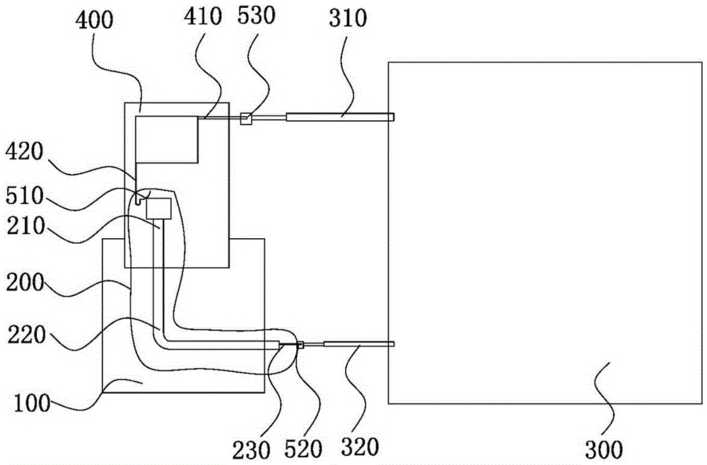
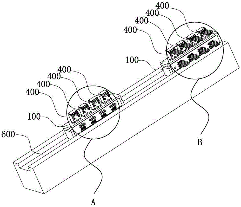
[0061] A mobile testing device for electronic components, including a carrying fixture 100 and a testing instrument 300 .

[0062] The carrying fixture 100 includes a conductor 200, and the conductor 200 includes an element connection end 210 for connecting the electronic element 400, an instrument connection end 230 for connecting the testing instrument 300, and an instrument connection end 230 for connecting the element connection end 210 and the instrument connection end 230. The connection part 220;

[0063] The detection instrument 300 is provided with a component contact part 310 for contacting the electronic component 400 and an instrument contact part 320 for contacting the instrument connection end 230;

[0064] The electronic component 400, the conductor 200 and the testing instrument 300 are sequentially connected to form a test circuit.

[0065] The carrying jig 100 is integrally formed as a carrying jig. The carrying jig 100 has good integrity and can firmly cla...

Embodiment 2

[0072] The main technical solutions of this embodiment are the same as those of Embodiment 1, and the features not explained in this embodiment are explained in Embodiment 1, and will not be repeated here. The difference between this embodiment and embodiment 1 is:

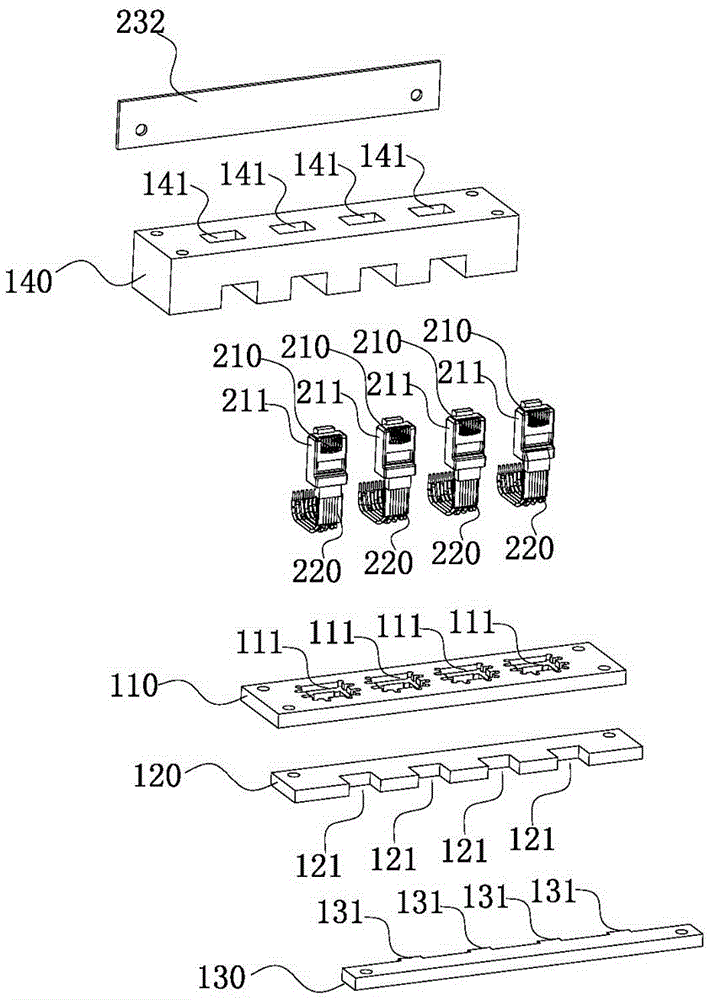
[0073] Such as figure 2 As shown, the component connection end 210 is fixedly connected to the connection plug 211 .

[0074] The carrying jig 100 includes a base 140 , a first splint 120 , a second splint 130 and an upper cover 110 . The base 140 defines a slot 141 through which the wire 231 of the component connecting end 210 passes. Both the component connection end 210 and the instrument connection end 230 are exposed outside the carrying fixture 100 , the component connection end 210 is connected to the electronic component 400 , and the instrument connection end 230 is connected to the testing instrument 300 .

[0075] The first clamping plate 120 and the second clamping plate 130 for clamping the compon...

Embodiment 3

[0080] The main technical solutions of this embodiment are the same as those of Embodiment 2, and the features not explained in this embodiment are explained in Embodiment 2, and will not be repeated here. The difference between this embodiment and embodiment 2 is:

[0081] Such as image 3 , Figure 4 , Figure 5 with Image 6 As shown, the instrument connection end 230 is connected to a circuit board 232 through a wire 231 , and the circuit board 232 is welded with an output terminal 233 . The wire 231 is welded to the welding point 2321 of the circuit board 232 , and the circuit board 232 is fixed to the carrying fixture 100 .

[0082] Specifically, the output terminal 233 is a metal probe. The metal probe is welded to the terminal hole 2322 of the circuit board 232 , and is electrically connected to the wire 231 through the soldering point 2321 by the wiring on the circuit board 232 . The setting of the output terminal 233 makes the connection between the instrument ...


PUM


Abstract

The invention relates to an electronic component moving test device and an electronic component moving test method applying the electronic component moving test device. The electronic component moving test device comprises a bearing jig and a detection instrument, and a conductive body is fixedly arranged on the bearing jig. The electronic component moving test method comprises the following steps: firstly, an electronic component is inserted to a component connecting end of the conductive body; secondly, the electronic component is electrically connected with a component contact part of the detection instrument, and the conductive body is electrically connected with an instrument contact part of the detection instrument to form a loop for testing; thirdly, the electronic component and the conductive body are respectively disconnected from the component contact part and the instrument contact part of the detection instrument after a test is completed; fourthly, the bearing jig inserted with the electronic component is moved to a workstation of the next detection instrument; fifthly, the electronic component is electrically connected with the component contact part of the next detection instrument, and the conductive body is electrically connected with the instrument contact part of the detection instrument to form the loop for testing; and sixthly, step two to step five are repeated until all tests are completed.

Description

technical field [0001] The invention relates to the technical field of electronic component testing, in particular to a mobile testing device and method for electronic components. Background technique [0002] With the continuous development of the economy, electronic products have become an indispensable part of our life. Therefore, the production of various electronic components has also made great progress and development. [0003] After the electronic components are produced, they have to go through an inspection process to test the various properties of the electronic components, such as: physical properties, electrical properties, environmental performance, etc. Among them, the test of the electrical performance of electronic components is a relatively important part. In the prior art, the test of electronic components is usually a separate test for each test item. This separate test method requires multiple pick-and-place electronic components, so Time-consuming and ...

Claims


Application Information

Patent Timeline
Patent Type & Authority Patents(China)
IPC IPC(8): G01R31/00G01R1/04
Inventor 陈伯榕
Owner 赣州市南康区弘达电子有限公司
Why Eureka
Try Eureka