Sintered gas-sealed optical fiber socket

An optical fiber socket and hermetic sealing technology, which is applied in the field of sintered air-sealed optical fiber sockets, can solve problems such as cracking, intolerance to harsh environments, and easy aging of elastic seals, and achieve simple structure, good air sealing effect, and good pressure resistance. Effect

Active Publication Date: 2012-10-17
南京全信光电系统有限公司
View PDF9 Cites 5 Cited by
  • Summary
  • Abstract
  • Description
  • Claims
  • Application Information

AI Technical Summary

Problems solved by technology

[0002] Under some specific working conditions, it is necessary to realize the airtight sealing of the optical fiber connector after installation, so as to realize the mutual air leakage or medium penetration between the two chambers with pressure difference or different medium chambers, and the sealing structure of the existing optical fiber connector generally adopts The end rubber seal or the O-ring seal between the pin and the housing, this type of sealing structure cannot completely prevent gas leakage, and is not suitable for waterproof and hydraulic sealing, and the elastic seal is easy to age, crack, and is not resistant to harsh conditions Hermetic fiber optic connectors are urgently needed in environments, airtight cabins and deep water conditions

Method used


Image

  • Sintered gas-sealed optical fiber socket
  • Sintered gas-sealed optical fiber socket

Examples


Embodiment Construction

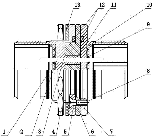
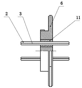
[0009] control attached figure 1 , which is characterized in that the optical fiber ferrule 2 is installed in the middle casing 6, the left casing 5, and the right casing 7, and the middle casing 6, the left casing 5, and the right casing 7 are respectively provided with pin holes, and the middle casing The pin holes provided in the body 6 , the left housing 5 and the right housing 7 are in clearance fit with the optical fiber ferrule 2 . Its structure is that the intermediate housing 6 is provided with a pin hole, the aperture of the pin hole is larger than the optical fiber ferrule 2, and after the optical fiber ferrule 2 is aligned with the axis of the pin hole in the intermediate housing 6, it is filled with glass medium 11, and the glass medium 11 is sintered and solidified to form a sealed whole with the intermediate housing 6 and the optical fiber ferrule 2, so as to realize the airtightness between the optical fiber ferrule and the housing.

[0010] The left and right...


PUM


Abstract

The invention discloses a glass sintered gas-sealed optical fiber socket. Optical fiber contact pins of the glass sintered gas-sealed optical fiber socket are mounted in an intermediate shell, a left shell and a right shell; contact pin holes are respectively arranged in the intermediate shell, the left shell and the right shell; the contact pin holes arranged in the intermediate shell, the left shell and the right shell are matched with the optical fiber contact pins in a clearance fit way; five-key grooves are arranged on circumferences at the inner sides of the left shell and the right shell; the five-key grooves position and guide a plug; an external thread is arranged on the left shell; and a mounting nut and a sealing gasket are arranged on the external thread. The glass sintered gas-sealed optical fiber socket has the advantages that the structure is simple and the gas sealing effect is good; a detachable shell design structure breaks through a difficult problem of grinding a sintered contact pin; a glass sintered structure has better compression resistance, ageing resistance and corrosion resistance compared with an elastic sealing component structure; the sintered structure is positioned and realized through a die; a more accurate contact pin mounting position can be obtained; two occasions that a connector prevents gas leakage and liquid leakage can be realized; and by means of the structures of the mounting nut and the sealing gasket, the connector simultaneously realizes the sealing at an open pore position after fixation and mounting.

Description

technical field [0001] The invention relates to a sintered air-sealed optical fiber socket, which belongs to the technical field of optical fiber connectors, in particular to a sintered air-sealed optical fiber socket. Background technique [0002] Under some specific working conditions, it is necessary to realize the airtight sealing of the optical fiber connector after installation, so as to realize the mutual air leakage or medium penetration between the two chambers with pressure difference or different medium chambers, and the sealing structure of the existing optical fiber connector generally adopts The end rubber seal or the O-ring seal between the pin and the housing, this type of sealing structure cannot completely prevent gas leakage, and is not suitable for waterproof and hydraulic sealing, and the elastic seal is easy to age, crack, and is not resistant to harsh conditions Hermetic fiber optic connectors are urgently needed in airtight cabins and deep water condi...

Claims


Application Information

Patent Timeline
Patent Type & Authority Applications(China)
IPC IPC(8): G02B6/38
Inventor 张欢朱钰郑木广王翠翠赖洪林陈祥楼
Owner 南京全信光电系统有限公司
Why Eureka
Try Eureka