Color film substrate and display apparatus
A color filter substrate and substrate technology, applied in instruments, optics, prisms, etc., can solve the problems of display brightness loss, light reduction, high price, etc., to enhance user experience, increase display brightness, and improve transmittance. Effect
- Summary
- Abstract
- Description
- Claims
- Application Information
AI Technical Summary
Problems solved by technology
Method used
Image

Examples
Embodiment 1
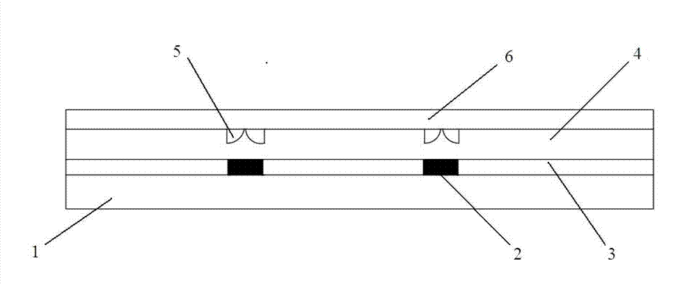
[0030] Such as figure 1 As shown, the color filter substrate of this embodiment includes: a glass substrate 1, a black matrix 2 and a color pixel layer 3 are arranged on the surface of the glass substrate 1, and an insulating layer 4 is arranged on the black matrix 2 and the color pixel layer 3; The insulating layer 4 is made of organic materials. A light refraction unit 5 is embedded on the surface of the insulating layer 4 , and a flat layer 6 is arranged on the insulating layer 4 , and the flat layer 6 is transparent. The refractive index of the light refracting unit 5 is set to be greater than that of the insulating layer 4, so that refraction can occur when the light passes through the two media. The light refraction unit is set correspondingly to the position of the black matrix 2, so that the light below the black matrix can be refracted to the pixel opening area mainly through the refraction phenomenon, so as to improve the light transmittance.
[0031] Specifically,...
Embodiment 2
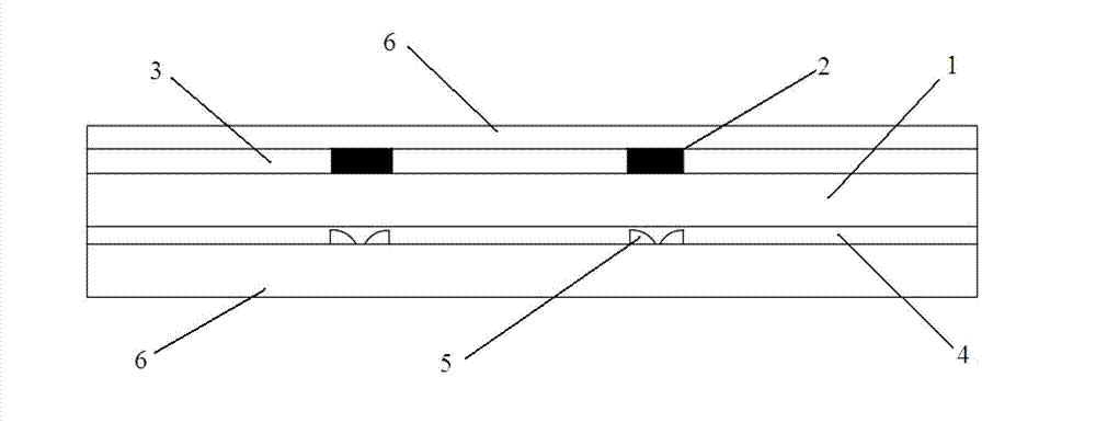
[0053] Such as figure 2 As shown, the color filter substrate of this embodiment includes: a glass substrate 1, a black matrix 2 and a color pixel layer 3 are arranged on one surface of the glass substrate 1, and a flat layer 6 is arranged on the black matrix 2 and the color pixel layer 3;
[0054] The other surface of the glass substrate is provided with an insulating layer 4 having the same refractive index as the glass substrate 1, and the insulating layer 4 is embedded with a light refraction unit 5, and the refractive index of the light refraction unit is greater than that of the glass substrate 1 (that is, the insulating layer). Refractive index, the insulating layer 4 is provided with a flat layer 6 .
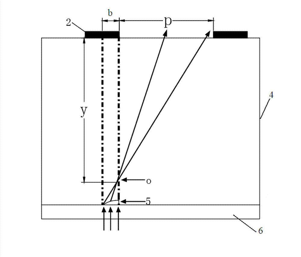
[0055] The specific light refracting unit is composed of two quarter lenses, the arcs of the two quarter lenses are oppositely arranged, and the opening direction formed by the two arcs faces the glass substrate 1 .
[0056] The calculation method of the arc radius R of t...
PUM
 Abstract
Description
Claims
Application Information
 - Generate Ideas
- Intellectual Property
- Life Sciences
- Materials
- Tech Scout
- Unparalleled Data Quality
- Higher Quality Content
- 60% Fewer Hallucinations
Browse by: Latest US Patents, China's latest patents, Technical Efficacy Thesaurus, Application Domain, Technology Topic, Popular Technical Reports.
© 2025 PatSnap. All rights reserved.Legal|Privacy policy|Modern Slavery Act Transparency Statement|Sitemap|About US| Contact US: help@patsnap.com