
Passive direct evaporation type cooling system for double-layer concrete containment

A double-layer concrete and evaporative cooling technology, which is applied in nuclear power generation, cooling devices, reactors, etc., can solve problems such as system boiling, and achieve the effect of easy engineering implementation and internal boiling of the system

Active Publication Date: 2012-10-17
CHINA NUCLEAR POWER ENG CO LTD
View PDF3 Cites 28 Cited by
  • Summary
  • Abstract
  • Description
  • Claims
  • Application Information

AI Technical Summary

Problems solved by technology

The other is to use the height difference and temperature difference between the cooling water tank outside the containment and the heat exchanger inside the containment to realize natural circulation and complete the cooling function of the containment after the accident. This scheme is easy to implement in engineering, but the cooling water tank must be installed in The position of the containment is higher, and the internal boiling of the system will only occur after the external cooling water tank reaches a certain temperature

Method used


Image

  • Passive direct evaporation type cooling system for double-layer concrete containment
  • Passive direct evaporation type cooling system for double-layer concrete containment
  • Passive direct evaporation type cooling system for double-layer concrete containment

Examples


Embodiment 1

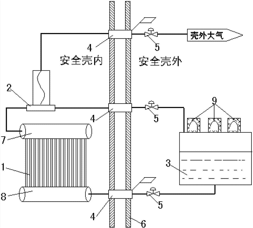
[0021] Such as figure 1 As shown, the passive direct evaporative cooling system for double-layer concrete containment includes a heat exchanger 1 inside the containment 6, and a heat exchanger 1 connected to the heat exchanger 1 through the The cooling water tank 3 outside the shell 6 and the heat exchanger 1 are provided with headers 7 and 8 for connecting a single light pipe. The heat exchanger 1 is connected to the steam-water separator 2, and the high-temperature steam generated by the heat exchanger 1 passes through the steam-water separator 2 and is directly discharged into the atmosphere outside the containment vessel. The steam-water separator 2 of this embodiment is located inside the containment vessel 6, and the steam-water separator 2 is connected to the ascending pipe passing through the containment penetrating piece 4 and communicating with the atmosphere, and is connected to the outside of the containment vessel through the descending pipe passing through the co...

Embodiment 2

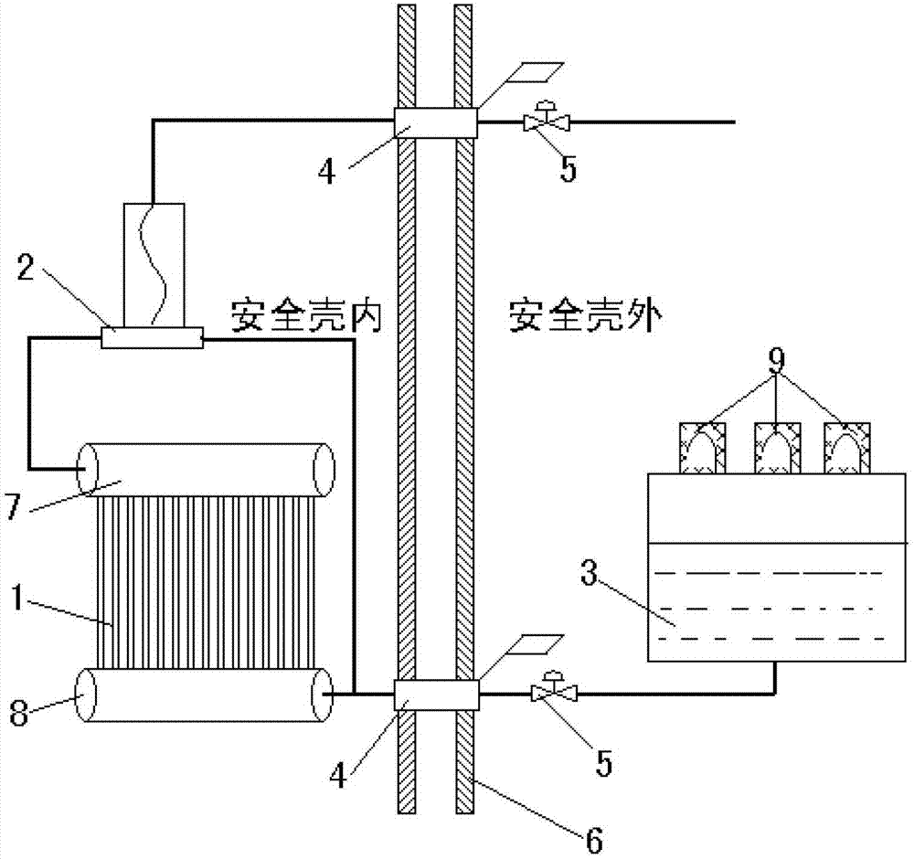
[0024] Such as figure 2 As shown, the passive direct evaporative cooling system for double-layer concrete containment includes a heat exchanger 1 inside the containment 6, and a heat exchanger 1 connected to the heat exchanger 1 through the The cooling water tank 3 outside the shell 6 and the heat exchanger 1 are provided with headers 7 and 8 for connecting a single light pipe. The heat exchanger 1 is connected to the steam-water separator 2, and the high-temperature steam generated by the heat exchanger 1 passes through the steam-water separator 2 and is directly discharged into the atmosphere outside the containment vessel. The steam-water separator 2 of this embodiment is located inside the containment vessel 6, and the steam-water separator 2 is connected to an ascending pipeline that passes through the containment penetrating piece and communicates with the atmosphere, and is connected to the heat exchanger 1 through a descending pipeline; the steam-water separator 2 Th...

Embodiment 3

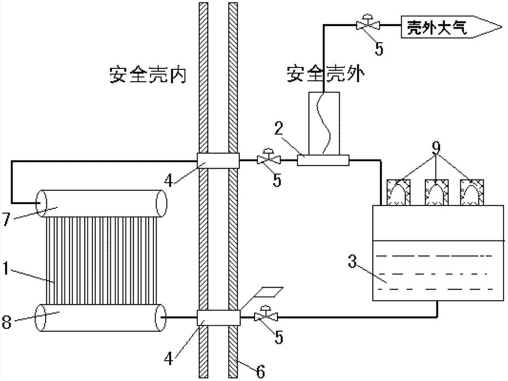
[0027] Such as image 3 As shown, the passive direct evaporative cooling system for double-layer concrete containment includes a heat exchanger 1 inside the containment 6, and a heat exchanger 1 connected to the heat exchanger 1 through the The cooling water tank 3 outside the shell 6 and the heat exchanger 1 are provided with headers 7 and 8 for connecting a single light pipe. The heat exchanger 1 is connected to the steam-water separator 2, and the high-temperature steam generated by the heat exchanger 1 passes through the steam-water separator 2 and is directly discharged into the atmosphere outside the containment vessel. The steam-water separator 2 of this embodiment is located outside the containment vessel 6, and the steam-water separator 2 is connected to an ascending pipeline connected to the atmosphere, and is connected to the cooling water tank 3 through a descending pipeline; The pipeline is discharged into the atmosphere, and the liquid water separated by the ste...


PUM


Abstract

The present invention relates to a reactor design technology, and specifically to a passive direct evaporation type cooling system for a double-layer concrete containment. The system comprises a heat exchanger arranged inside a containment, a cooling water tank arranged outside the containment, and a steam water separation device. According to the present invention, the retention time of cooling water in the heat exchanger is increased to force the cooling water to generate a phase change, and a large amount of heat inside the containment is taken away through phase change latent heat of the water; when the temperature of the containment is less than 100 DEG C, natural circulation flow of the system is low or zero; when the severe accident is generated in the nuclear power station and the containment temperature is more than 100 DEG C, water inside the heat exchanger is heated and expands until the water is evaporated, the separated water returns back to the cooling water tank, the steam is discharged into the atmosphere outside the containment, the system is put into operation, and the natural circulation is formed. With the system of the present invention, the whole process does not require intervention by nuclear power station operators, and whether the system is put into operation is automatically selected according to the containment temperature, such that the passive system is completely achieved, the human intervention factor during accident generation is substantially reduced, and the containment cooling function is achieved independent of external energy sources.

Description

technical field [0001] The invention relates to reactor design technology, in particular to a passive direct evaporative cooling system for a double-layer concrete containment vessel. Background technique [0002] Since the 1980s, the United States, Japan, France, Germany, Russia and other countries have carried out research on passive technologies, among which the AP1000 third-generation nuclear power unit of the passive safety advanced nuclear power plant is the representative. Regardless of safety or economic considerations, it is the general trend to use passive containment heat removal system to improve the safety level of nuclear power plants. The passive containment heat removal system is adopted to ensure the long-term heat removal of the containment in the case of accidents beyond the design basis , can maintain the integrity of the containment vessel and mitigate the consequences of severe accidents. Make the reactor reach or have the safety level of the third gen...

Claims


Application Information

Patent Timeline
IPC IPC(8): G21C15/16G21C15/18
CPCY02E30/40Y02E30/30
Inventor 王志刚李军王晓江邢继
Owner CHINA NUCLEAR POWER ENG CO LTD
Learn More