Separately-charging battery charger
A battery and charger technology, applied in battery circuit devices, current collectors, instruments, etc., can solve the problems of no application advantages, increase charging energy consumption, etc., and achieve the effect of improving charging quality and prolonging service life
- Summary
- Abstract
- Description
- Claims
- Application Information
AI Technical Summary
Problems solved by technology
Method used
Image
Examples
Embodiment
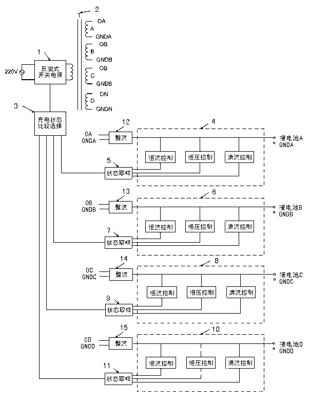
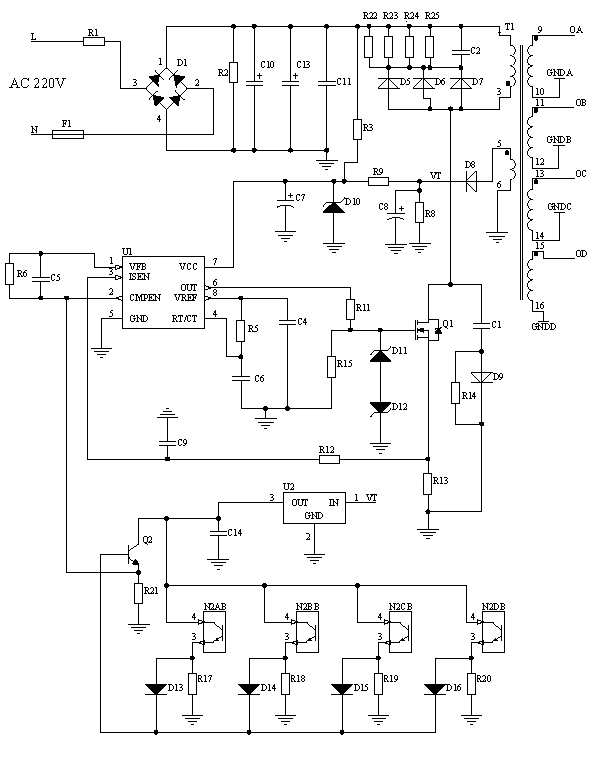
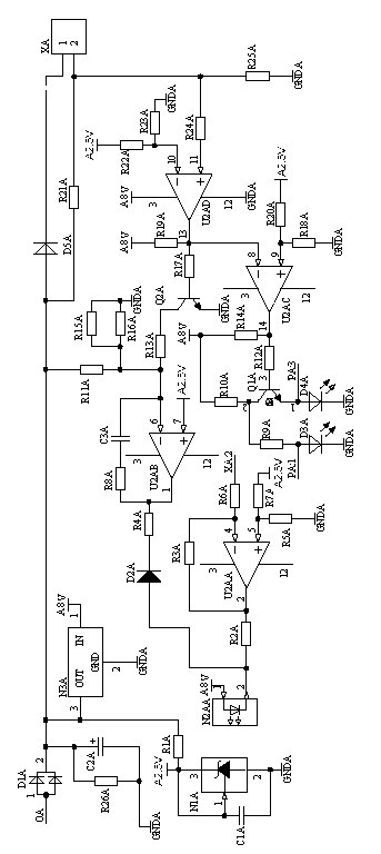
[0035] Example: such as figure 1 - Figure 6 As shown, the sub-charger includes:
[0036] A high-frequency flyback switching power supply (1) is composed of a pulse width modulation control integrated circuit U1 (UC3842) and a MOS field effect power transistor Q1 (IRFT460) as the core.
[0037] Balanced output high frequency transformer T1 (2).
[0038] The charging state comparison and selection circuit (3) is composed of transistor Q2 (C1815) and diodes D13, D14, D15, D16 (both 1N4148).
[0039] The A-way constant current, constant voltage and trickle charge control output circuit (4) is composed of a four-voltage comparator integrated circuit U2A (LM339) and a transistor Q2A (C1815).
[0040] The charging state sampling circuit (5) of the circuit A is composed of the photocoupler N2A (PC817).
[0041] The B-channel constant current, constant voltage and trickle charge control output circuit (6) is composed of a four-voltage comparator integrated circuit U2B (LM339) and ...
PUM
 Abstract
Description
Claims
Application Information
 - R&D
- Intellectual Property
- Life Sciences
- Materials
- Tech Scout
- Unparalleled Data Quality
- Higher Quality Content
- 60% Fewer Hallucinations
Browse by: Latest US Patents, China's latest patents, Technical Efficacy Thesaurus, Application Domain, Technology Topic, Popular Technical Reports.
© 2025 PatSnap. All rights reserved.Legal|Privacy policy|Modern Slavery Act Transparency Statement|Sitemap|About US| Contact US: help@patsnap.com


