

Medical guidewire
A medical wire technology, applied in the field of medical wires, can solve problems such as damage to blood vessels and other organs, loss of flexibility, etc., to achieve the effect of improving firmness and ensuring flexibility
- Summary
- Abstract
- Description
- Claims
- Application Information
AI Technical Summary
Problems solved by technology
Method used
Image

Examples
Embodiment 1
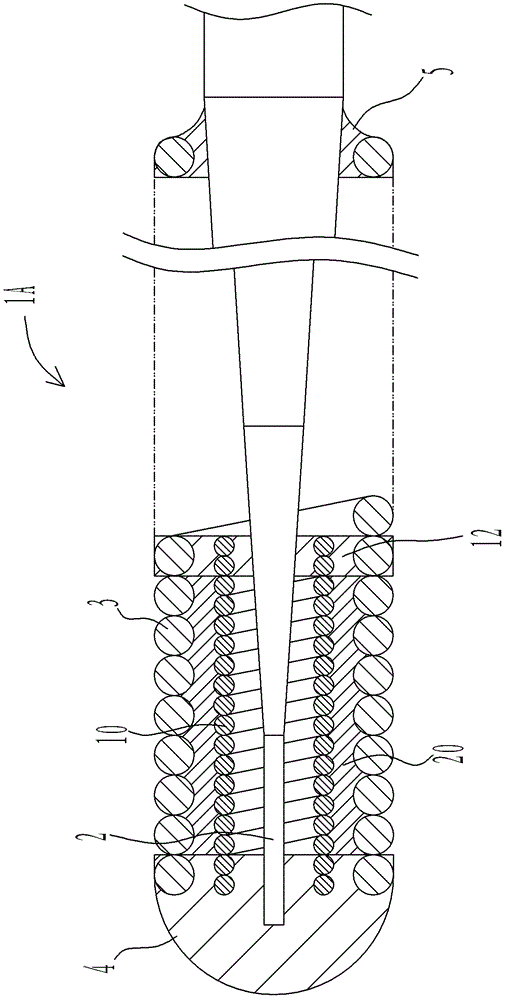
[0034] Such as figure 1 As shown, the medical guide wire 1A has a mandrel 2 in the shape of a round bar with a small diameter at the distal end and a large diameter at the proximal end.
[0035] In addition, an outer coil 3 is fixed to at least the front end portion of the mandrel 2 . Specifically, the outer coil 3 is composed of a single-strand coil tightly wound at least at the front end, and the front end of the outer coil 3 is connected to the front end of the mandrel 2 to form a substantially hemispherical front end 4 . In addition, the base end of the outer coil 3 is fixed on the mandrel 2 through the first fixing part 5 .
[0036] In addition, an inner coil 10 is disposed inside the outer coil 3 , and the inner coil 10 covers at least the front end of the mandrel 2 . The inner coil 10 is composed of a single-strand coil tightly wound across the entire length, and the front end of the inner coil 10 is connected to the front end portion 4 . In addition, the base end of...
Embodiment 2
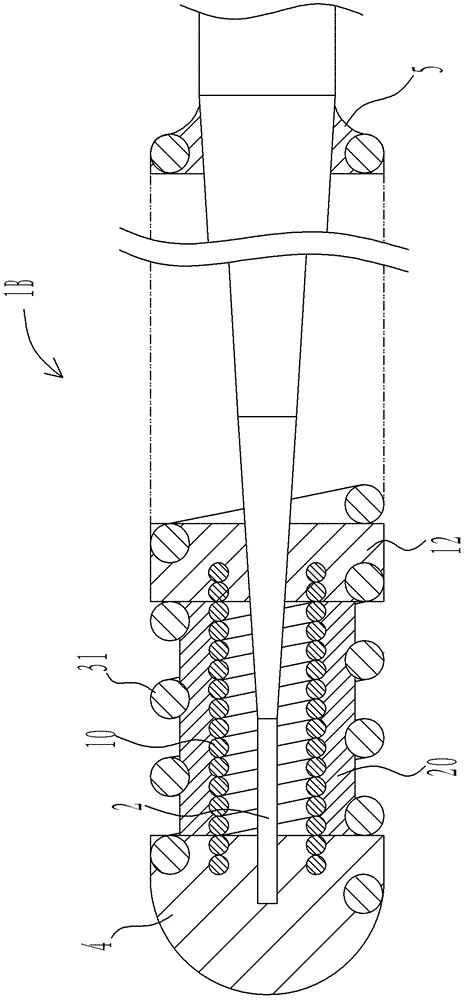
[0045] Below, refer to figure 2 The medical guide wire 1B of the second embodiment will be described, and the description of the same parts as those of the first embodiment will be omitted, and the same reference numerals will be assigned in the drawings.
[0046] Such as figure 2 As shown, at least the front end portion of the outer coil 31 is loosely wound, and gaps are provided between the coil wires at the portion corresponding to the resin layer 20 .
[0047] In this way, at least the portion of the outer coil 31 corresponding to the resin layer 20 is loosely wound, so that the resin material constituting the resin layer 20 can be easily filled from the gap between the coil wires of the outer coil 31 . Therefore, the formation operation of the resin layer 20 is smoothed, and the productivity of the medical lead wire 1B is remarkably improved. In addition, on the outer coil 31 , the part corresponding to the resin layer 20 may be loosely wound or partly loosely wound, ...
Embodiment 3
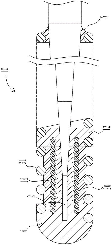
[0049] Below, refer to image 3 The medical guide wire 1C of Example 3 will be described, and the description of the same parts as those of Examples 1 and 2 will be omitted, and the same reference numerals will be assigned in the drawings.
[0050] Such as image 3 As shown, the inner coil 14 is composed of a multi-strand coil formed by twisting a plurality of coil single wires. In addition, even when the multi-strand coil is meandered or bent, it has a so-called property that the deviation of the single wire is small, and has high firmness.
[0051] When the inner coil 14 is formed of a multi-strand coil as described above, the firmness is improved with the formation of the resin layer 20, and at the same time, the firmness of the distal end portion of the medical guide wire 1C is greatly improved. In addition, since the winding angle of the coil single wire of the multi-strand coil relative to the central axis of the medical guide wire 1C is smaller than the winding angle ...
PUM
 Abstract
Description
Claims
Application Information